Hmmm… I was really talking about driver PCBs, but I don’t have any lights with illuminated tail-caps, so I may have to take you up on that offer.
Outdated doesn’t bother me too much, as long as the board at least works, and there is still firmware around to support it (in the case of a driver board). And size isn’t an issue either. I could probably find a use for just about any size board you guys might have around.
I have some of wights boards sitting around that won’t get touched now that we have triple channel too, just not as many. The offer was serious and still stands, just PM if you really want them. I don’t want to take this thread any more off topic
Ok, here is a 46mm Texas Avenger in SRK / Q8 Size. It is the same as a Q8 V5.1 driver except with the added bank of 7135’s and a slightly differnt pinout to match the rest of the Texas Avenger series.
All the pads are 0805, except the OTC / E-switch whch is 1812.
Full copper pour including nice heavy pour from the ground ring to under the MCU. This should help the internal tempreture sensor if it ends up being used.
It also has a zener even though it is useless for an e-switch light, simply because I can.
It has a total of 16 7135’s, 1 on the single channel and 15 on the bank. Total they are capable of regulated currents of 350mA - 6A depending on how many you install and if you use 350 or 380mA versions.
That should net you around 1800-2000 lumens of regulated power depending on the LED’s. Naturally the FET is there as well and can handle up to 50A.
I considered the file down tabs but honestly I found them to be more of a pain then they were worth in the drivers I built. I still had to glue most of them down to keep them from popping out after repeated use. I can add them easy enough if others have had better luck.
The LDO I also considered but seeing as I plan to design a 2s/4s driver and it would take so much modding in order to convert this one to do that I decided against it. It is just not worth the effort to convert this driver to 2s/4s IMHO.
As far as the other options go, I didn’t see much that would be useful, an external temp sensor is great but can also be installed on the R1/R2 pads, same for indicator LED’s or anything else, those pads allow for anything you may desire from an optional standpoint.
I also wanted the schematic to match the other TA drivers.
If you can think of something in particular that would be nice to add to this one please do let me know, I can add it if it is worth it.
Oh yeah, I was thinking when building this driver and realized that when using the internal voltage reference for LVP there is no need for me to change the board designs, except maybe on the 17mm.
The R1/R2 pads allow you to use that pin for anything you may desire as you have both pin/ground and pin/positive between those pads for expansion. So they could be used for external temp sensor, indicator LED or whatever.
EDIT: Yep, just checked the 17mm, without a complete re-design it would not free up any significant amount of space, so just gonna leave them as is
Here is a 2S2P or 4S version of the Q8 / SRK Texas Avenger
TA46S : 46mm Skyray King 2S2P or 4S XHP / MTG2 Driver
This is the same as the above driver except it comes setup for 2S2P and 4S setups.
It is a classic SRK driver but setup for 2S/4S 6V/12V LED’s (or 2/4 LED’s in series). So this is what you want for an XHP35 (although for an XHP35,be warned, they generally die very quickly if an FET is used) / XHP50 conversion.
The ring on the outside bottom is connected to the 1st cell positive to give the MCU 4.2V. The LED gets the full 2s or 4s voltage, this allows you to use the driver without an LDO or zener.
You will need to bridge the bottom side pads according to what setup you will be using 2s or 4s. I recommend just going 4s unless you need to do 2s for some reason. You can either just solder bridge across the pads or use 0 ohm 0805 resistors to bridge. Follow the silk screen on which pads to bridge.
You will also need to modify the tailcap PCB/setup so that the cells will be in the desired 2s2p or 4s setup and so cells can be installed from the rear of the light. Don’t forget install springs on the driver pads to keep from damaging the driver when dropping the batteries in, plus you then don’t need button top cells.
The 1st cell that conects to the ground pad on the driver needs to have it’s positive end connected to the flashlight body., then obiously match up the cells acording to what you are doing. Yes, this does require you think for yourself, this is an in depth mod, you need to understand what you are doing.
Otherwise it is the same as the rest of the drivers. It does not have a Bleeder resistor and the zener is useless.
In 2S2P and 4S version, the outer ring needs to be the - of only one or two battery with 4,2V, isnt it?
Is there a need to make a Connecton where you have written 2S2P or 4S, if I want to use this battery configuration? And connections between all 4 pads for 4P ?
No, the outer ring is the Batt+ from a single cell. If you look at the bottom of the PCB, there are markings for Batt+ and Batt- on there. Those markings indicate which orientation those two cells need to be in order for the driver to work. The other two cells will be oriented differently for 2S2P vs 4S connection. Anyway, the Batt- pad is the cell which TA is calling cell one and that cell’s positive end must be connected to the outside ring of the driver. Then, you’ll end up with only one Batt- but two different Batt+ connections. One Batt+ which is only a single cell, and the other Batt+ will be either 2S2P or 4S, according to your chosen configuration. Clear as mud now?
I started out splitting the grounds but TomE brought up some good points and we determined that splitting the positives instead would be the better option.
If you combine the multi-cell driver with the SRK tailcap PCB, you will have everything you need to set it up for multi-cell use. Just make sure you understand how to setup and align the cells.
Both the driver and tailcap are labeled with what pads need to be bridged in order to make it work with the setup you want.
Also, the multi-cell driver can NOT be used in 4P mode, it will short out.
I think maybe he meant to write “make quick scratch” by which he would mean to sketch up a quick drawing to show how the 4S and 2S2P configurations would actually be arranged in the light using your driver and tail PCB designs.
Ah, yeah I was thinking about that yesterday, the issue is with such a design it is hard to make it clear in a picture without laying it all out. I guess I could do that and people can figure out how it fits together in the light.
The 4P driver is simple, just like a normal SRK driver, simply bridge the 4P resistors on the tailcap PCB.
Well finally got some time and made up a DO1 driver. Let me know if ya’ll spot any issues!
TADO1 - 38.5mm : This is a driver made specifically for the DO1 but might fit other flashlights as well. It is 38.5mm as you can tell. Same as all the other drivers except that all of the 7135’s have been moved to the top side of the driver and the contact ring on the bottom is sized to allow the batteries to make good contact.
The OTC pads have also been upgraded to 1206 pad sizes since it is an e-switch light and this will make it easier to setup. Although you could use it as a clicky driver as well.
Thanks I understand. Only in 1S4P gets the Driver max 4,2V over the negative of the red Cell1. And here is the body of the flashlight used to deliver the negative of this cell.
In 2S2P mode the driver will get 8,4V and the Attiny is protected with zener and the AMCs does not need to be protected. The body of the flashlight does not ave any potential and is not needed to make contact between tail PCB and driver PCB.
Not quite. First off like I said before, the TA46S series cell model can ONLY be used with the cells in SERIES. It CAN NOT be used in 1S4P mode.
The same goes for the Normal TA46, it can ONLY be used with the cells in 1S4P and can not be used in series.
Now for the multicell setup on the TA46S. If you follow the crude diagram you see that it is actually the positive from the 1st cell (the cell that terminates on the negative pad of the driver) that connects to the body of the flashlight through the 1s4p connection on the tailcap.
It is simply using that connection, it has nothing to do with 1S in this case though (I should have added this to the silk screen but didn’t think about it at the time).
The series then continues on like normal until it terminates at the positive pad of the driver.
This feeds the MCU 4.2v while the LED gets the full 16.8V
The same goes for the 2s2p setup, except max voltage is 8.4V.
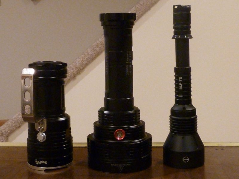
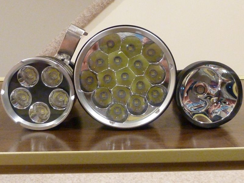
I need, or plan to use the LDO SRK driver in this light, center. It's 2S3P stock, and an SRK driver fits perfect:
Driver stripped - was gonna piggyback one in, but a full replacement is nicer, easier:
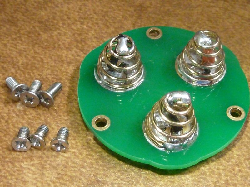
Tailcap with stock stripped screws and replacements:
It's 16X - posted bought it in the what did you mod today thread. Today I spent the big bucks and ordered 20 XHP50's, bin K2, 5700K. Figure 4 extras. Got a custom plate/shelf made by a machinist out of alum to mount the MCPCB's on - alum was free and they are set up for it, copper would have been an issue - getting material, etc.