You are right its a problem Oshpark has with one of its fabs.
It is no problem to get a refund
or another order with right rings.
Also its a problem to TA design in Diptrace
Here is an example I have for drivers which often came on top side without ground ring.
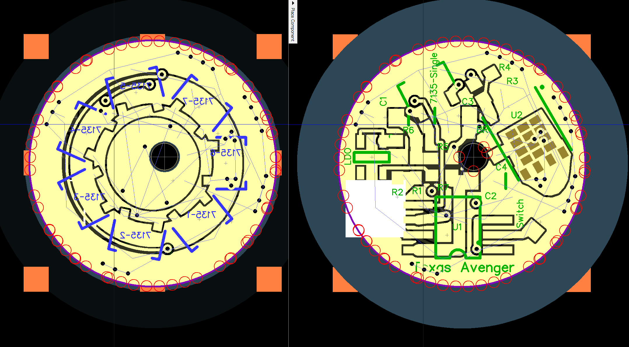
You can see the top solder mask goes beyond the board and causes in one fab problems with nearby boards on the tray so they remove it.
I received today a reply which says the only solution they have for now is to get em assigned to super swift service to get em to the right fab.
This is the reply I received just an hour ago.
after I read your ticket I am sure I can adjust Texas Aces design to keep the solder mask within the board boundaries, he usually had em far off the edges
left new design right old TA design
Indeed it seems those >1S HD resistor values aren't exactly available in smd.
I thought I'd checked. Oh. well. But I'll try to post some re-rounded numbers soon. That 3S rounding you post will make full scale about 4.1 V/cell (pegged above that), not too bad and the calibration can still be adjusted to be right for cells below that voltage, but getting a little closer would be nice so I'll put it on the list to see. I would generally tend toward rounding the other way, but it's not a simple as just choosing the next value up, which may be too far, need a different combination.
It seems the 2250 was just a mistake. The value that exists is 2260.
Rounding to 5% values is not a great idea here for >1S builds, and there's no reason not to buy something like a 2260. They cost the same (ten for $0.15 ) and are on digikey the same as 2.2K is. I'll review the values though to make sure I list ones that actually exist. Can you use a 22K if you've got it? Sure, but most people won't have the 1500 on hand and will order new anyway. You're going to loose 0.1V and and without giving detailed instructions, you're also going to be off in your overall calibration by 0.1V
Edit:
Hmm, just realizing, we originally planned the >1S builds to work with a low leakage LDO. I think we decided that required a new LDO footprint, but in the end we went with a diode after the LDO for most boards, which I may not have corrected for anyway. I'll review it.
Also the toykeeper repository is probably way out of date. You mention that possibility though, so that's cool. I do also point to it on my thread in case I disappear and other people make updates, but there were a few bugs during development releases around the time I believe she updated that, and some of those were show stoppers. I try to point on the HD thread which releases are best tested (at the time of those bugs I was pointing out previous versions as being better tested for instance). Presently that would probably be v1.4.1
I should probably put a version tag in the source directory so I can even tell which version she has posted. She did mention having tested it some though, so it might be a good version.
Interesting, at least we finally have the reason for some of the driver working and others not.
It is a fairly simple fix, I just never considered it having an effect like this. It was easier to oversize it and not worry about if it is was perfectly lined up.
Looks like Lexel already fixed the SRK size, I will see if I can find time to fix the others and update the OP in the next week or 2.
So the typo (my typo) was that it should be 2550 not 2250. Looks like a typical kind of typo.
2550 does exist, is just as easy to order as 2200 and produces the right value dead on.
The rest are all correct in the manual and they do actually all account for the diode (so they aren't correct when the diode isn't used, but they can work, better wrong that way than the other way).
So with this typo fixed, the un-rounded numbers should definitely be put back. All of these values exist on digikey for the same price as E12 series resistors. Why add another 0.1V error to people's calibration, and range if it's not needed. You're buying new resistors anyway, just buy the right ones.
For the 1S build anything close will work. For the >1S build the usual tolerance range just isn't there. The specced values will exactly max out the ADC at a full battery. We could lower it by 2% since the headroom at the top is strict but at the bottom it's just a spec, but making fit exactly isn't bad either. Calibration is 255 full scale, simple, and no calibration is needed assuming the LDO tolerance is pretty tight, not sure on that but it's probably much better than the attiny references we usually use.
Fortunately the typo was for 3S, and I guess there aren't many 3S lights.
With either the LDO or zener, or neither, but not both. (with zener being the hack and not OTSM compliant, and well not actually on at least most of these boards)
I updated the OP with a license statement, I meant to do this a long time ago but just never got around to it. Nothing real surprising, it is an open source project after all.
First thing to do is make sure that power is getting to the driver properly. I usually start by directly applying power to the spring and ground ring with some alligator clips.
If that doesnt work then start tracing the power and see where it stops.
Also a lot of times simply reflowing the driver again can fix things.
The most common issue I have had was a 7135 either shorted out directly or the ground pad on the 7135 shorted out to one of the vias. If you used too much solder paste this is what I would check.
Start pulling the 7135’s off 1 at a time and see if it starts working. The bottom side 7135’s are the most common to have an issue.
In some cases I simply write off the driver and start over, for a few bucks it is just not worth spending too much time on it.
LIke TA said hook up power with alligator clips. Check voltage at the + side of the LED. If you short from the big fet pad to the ground ring the LED should light (I just use pointy tweezers). I'd be surprised if that doesn't work but it's the first test. Then, still hooked up the same, but also apply battery voltage with a probe tip to the FET gate pin. If the pin row is on top, it's the one on the left. That should light up the LED. If not, there's a problem with the fet or more likely its soldering. If it does, there's a problem with the mcu's ability to control the gate voltage, which as TA says could be from the 7135 or something else being shorted down somewhere, so then the number of places to look expands pretty fast. Since none of the channels work though, that's probably where you end up.
Measure voltage on the high side of C2, make sure it's not pulled down.
Measure voltage between R1 and R2: for non OTSM it should be, I'm not exactly sure but probably something like 0.8V. For OTSM it should be higher than 2.0V. If these are wrong, it can cause the software to shutdown the light.
Check that your mcu isn't on backwards.
Start with all that and see what you see, then can consider more.
Banggood contacted me about making a replacement driver for the S42 (since the stock driver is Horrible). After some back and forth I finally got enough info to start working on the driver and charging circuit.
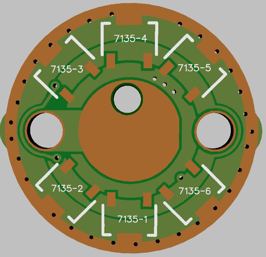
Here is a first draft at a replacement S42 driver. It uses the standard TA layout minus the components that would not be used in the S42 (zener, voltage divider ect).
I am going to try to get them to do a spring bypass from the factory but if not I plan to leave the hole in place to make it an easy mod. I am not sure if they will let me leave the bottom side 7135 pads on it, they will not be populated for sure and honestly I don’t think it would even be wise to populate them. There is no thermal path for them to get rid of the heat and as such would just thermal throttle anyways.
I am debating removing the bottom side 7135’s completely.
Driver PCB:
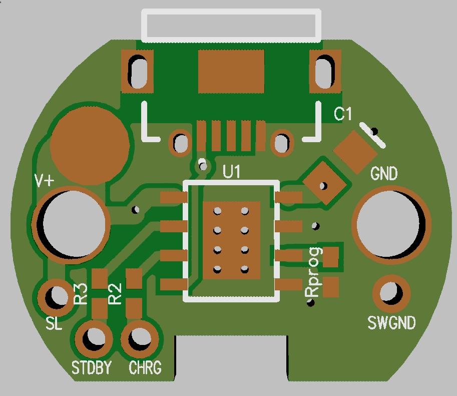
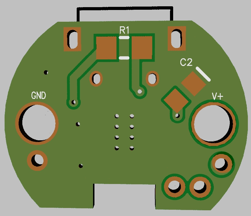
Charging PCB:
The charging circuit is based on the LY4057 chip, it is a 1% tolerance linear charging IC that should work fine. Still debating what to set the current to. It can do 1A but it will overheat and reduce the current over time at that level anyways. So thinking that ~500ma would be better, it has a much higher chance of not throttling this way.
I will post these designs once they are done for those that want to update the V1 S42.
the thing is that its reversed to the original bolt polarity of the S42 driver, so it need to get inverted to get compatibility to the original slave board if people just want to replace that and keeping old slave boards
The AMCs output lane is pretty thin, but should be OK
Thank you for sharing this driver, TA! I haven’t received my S42 yet and I am looking forward to testing it first. But, from what I read so far on BLF, the stock driver/FW is not up to our expectations