I don’t think I do, but I will have to check.
I have around 20-30 pcs… let me know if you need. but it will take time to reach you :email:
Or I could just use one single .025 resistor? Digikey has those. They look to be 1206 size. 3mm x 1.6mm
Thank you for the kind offer, but Digikey has most everything and I can get them in a day or two.
yes you can use single 0.025 ohm. Remove all exiting 0.1 resistors
That ain’t subjective… everybody with at least half a taste bud knows it’s chocolate… :party:
So does Mouser… and being local you will have them the next day. I once ordered something from them in the morning and it was here by the afternoon.
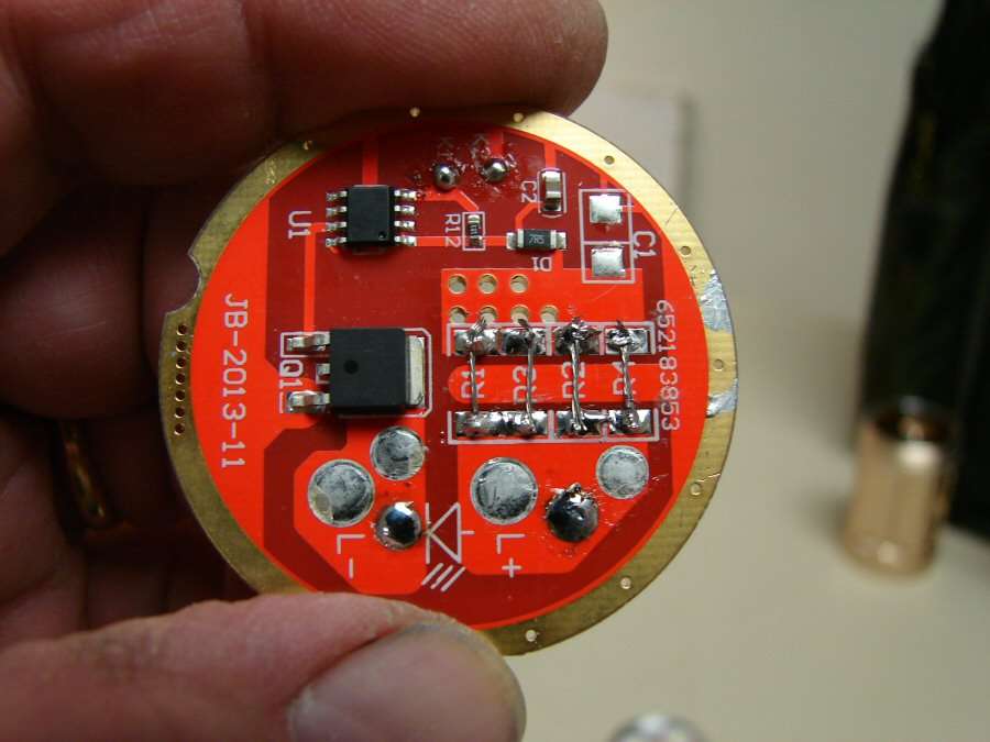
I had one of those drivers that had this setup stock:

even 0 ohm resistors have very little resistance, they put 000-ohm on this driver.
did you measured drive currents?
See L3 channel…
there are 4 resistors. because that channel under driven due to long track between FET & sense resistors.
this is why they put another resistor to balance. old buck driver SRK also have that issue.
Interesting, so maybe it would be good to check each channel’s output before signing off on it. Hope I remember to do that on the bench before assembly.
That one was not well balanced at all, stock it was like this:
L1+/L1- 2.20A
L2+/L2- 2.60A
L3+/L3- 2.08A
Power from 4x 18650 in parallel, checking output one channel at a time on the same LED (so it wasn't due to different LEDs having different Vfs causing the skew).
edit: and all 3 channels had the same 3x 1R0 + 1x 000
L3 channel has long track between resistors and FET. make it reduced output. to improve its current, solder thick copper wire to it.
other two channel difference is due to these sense resistors not 1% or 5% tolerance.
So it needs a jumper from the L3 sense resistors to the bottom left pin on the 7136? Would you leave the original PCB trace intact or sever it (would it make a difference)? L1 & L3 are good as-is, correct? And then mess around with the resistors to get the target output & balance the 3 sectors.
i think this comment says it all… :party: it is so true……i couldn’t have said it better myself
XML rated maximum drive current is 3A but some noticeable output improvement over 3A too. but after 6-7A difference is very small. so 6A to 11A no improvement at all. may be reduced output due to higher junction temperature.
yes. disconnect original trace between FET (s pin) to 7136 left pin.
or
sense resistor to left pin of FET (Source pin) then no need to disconnect original trace.
11A into 3 LEDs in parallel is only 3.6A each. And the old rules-of-thumb are out the window with the LEDs on copper.
i like the sound of that “ONLY” 3.6A…that’s the spirit…if we wanted light with “ENOUGH” lumens we wouldn’t be on BLF in the first place…
But, 11 amps is out of this driver,
Not this driver,

I Switched Drivers. I used the driver from the Securitylng in this light and I will be using the driver from this light into the Securitylng.
Just in case we all aren't on the same page.
If we weren’t all on the same page, we wouldn’t all be reading this… J)
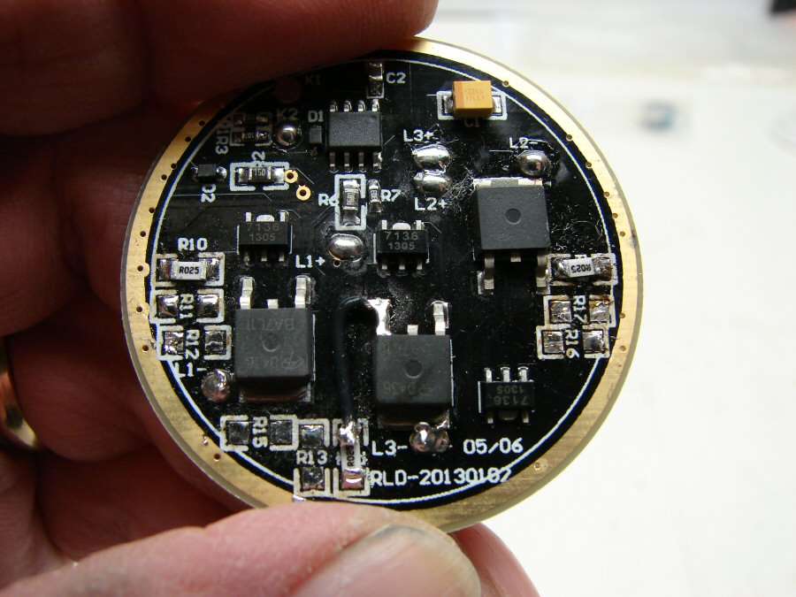
Modded the driver with R025 resistors and wire on the L3 run.
5+ amps overall, as a result. Didn't check each zone.