You can calculate 300 Lumens or less per emitter for most of those lights
This one has 4 emitters , i`ve bought it 2 times so far and i can hornesly say its maybe the best SRK based torch in existance( atm ofc) , and i bought many
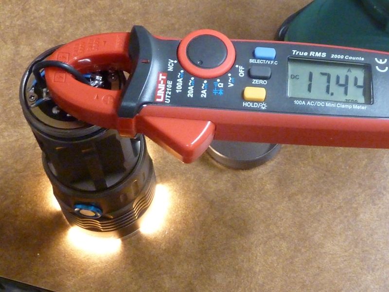
At start it runs at 10 amps( 35k cds measured at 3m) . The driver has a temp control too, yet the body dont have solid emitter base but for 30 or something $ its a great light indeed
The display shows l-m-h modes AND battery charge left( 9,8 ,7 est)
Hi Mitko, I take it these emitters are real XM-L2 U2 & what do you recon the output is, about 3000 lumen ?
Another question, how do you take tail amp readings on a parallel 4 cell set up ?
I am wondering if there is an easier way than the way I do it ?
Yes they are: the tint is ….quite pure white, without any blue/green/purple minor tints in it
Well i actualy took the reading via a single high amp 26650 cell and an open torch ![]() Prolly using 4x high amp 18650 would give a better current, yet from my experience and the lux readings that i measured( like 35k ) i would say its a very very good SKR based light by default- pay attention that those readings drop fast cause the light overheats
Prolly using 4x high amp 18650 would give a better current, yet from my experience and the lux readings that i measured( like 35k ) i would say its a very very good SKR based light by default- pay attention that those readings drop fast cause the light overheats
The default driver is quite interesting too
You know, a custom made 3x XML2 SRK/ w 46mm fet dd driver gives like 35k cds , this one too
I see :+1:
What I use for tail cap readings on 4 x P cells is a lead I made up myself.
12mm x 5mm neodymium magnet with a 4mm hole in it with a 16awg wire through the hole so that the bottom of the magnet squashes the wire onto the cell negative with the wire soldered on the top of the magnet in the countersunk hole.
4 of these with the 4 x 16awg wires soldered to a 12awg wire to pass through a clamp meter & on to the lights tube.
I was just wondering if there was an easier way ![]()
Anyway I think that I may order one of these.
From what you say heat dissipation is a problem as usual.
What is interesting about the driver ?
Rubber band 4x cells together. 3 strips of copper plate 30gauge works decently. Bend both ends of 2 of the strips to where the center of the strip is raised and the ends sit flat on 2 cells. Third strip bridges the two bent strips. Clamp meter + wire loop connect the central bridging strip to the negative contact of the underside of the driver.
So I take it that you have to hold these copper strips in contact with the cell negatives & also the wire on to the negative driver contact ?
With the magnets I don”t have to hold the wires in contact with the cell negatives just the wire to the light body.
” I could’ve sworn someone reviewed this style light with the display and side switch, can’t seem to find the thread though.”
I would be interested in reading that review ![]()
Or if you like get a powerful regulated DC power supply for testing
If you bend the strips properly then very light pressure (with one end of the wire loop) on the middle strip holds everything well. Just a simple method. Could be improved with soldering/magnets, but I don’t measure enough 4P lights to justify it.
yeah it’s the same just 7x xm-l2
Got 2 of these, one with dd, the other laying in parts,haha.
I only made my lead up in anticipation of testing the Q8 (to much time on my hands I suppose) ![]()
I have tried it on a 4 parallel cell battery pack I have for a headlight & it works well :+1:
It is a 4 wire/magnet variation of the single wire/magnet I use for measuring the tail amps on tube lights.
By not having to hold anything in contact with the cell/cells I have a hand free.
I might try making up a magnetic & soldered version of your 3 copper strip set up as this year I can see me getting several 4 parallel cell lights :person_facepalming:
Thanks for the idea :+1:
Here is the shunt I made for testing SRK’s:
Once calibrated it is quite accurate. I explained how I did it in the DPS5015 thread.
interesting.
And that quad looks nice.
Though I wait for the Q8, and have the Nitecore TM06S with very nice output, UI and smart button to show voltage to play with in the mean time ![]()
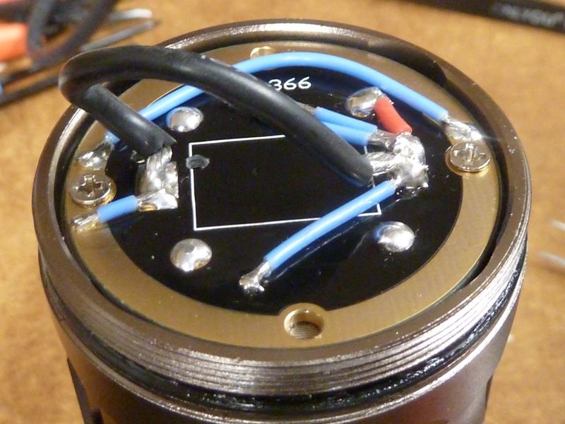
I mod the tailcap to measure tail amps with a clamp meter - some cuts and jumpers, and adding a 18 or 16 AWG wire loop, built in permanent. This way, it's a true measurement, just pop the cap off and clip on the meter - no fooling around. I've done several SRK's this way.


Bout that UltraFire SRK with the display, I'd love to know more details - whether it has a shelf, how the switch is wired up etc.
How does that work? isn’t everything in the vicinity of the tailcap area all -Batt?… and with 4-P cell arrangement, how is all the current passing through only the black wire?
Ahh, easy. Just trace it out, and ensure you got two contact points - one for all the cells wired, the other for the screws/screw mount to the body. Then inter-connect those 2 points with a heavy gauge wire. This will require cuts and jumpers typically. I took detailed pics on my recent one. Need to upload. On that one, it had traces on both sides on the MCPCB, so had to cut a lot of traces.
Have you got a link for that explanation ‘T_A’…. I can’t seem to find it. ![]()
G'Day Teacher, ![]()
AFAIK it it may be here:
Budget friendly adjustable bench Power supplies perfect for testing LED's and other uses!
https://budgetlightforum.com/t/-/41323
Best Regards,
George
Thank you George……. :+1:
![]()
Here is the link to the page with the shunt explanation: Review of DP50V5A & DPS3012 bench top power supply modules, best bang for the buck around!
Sorry, never got an email for this thread.
