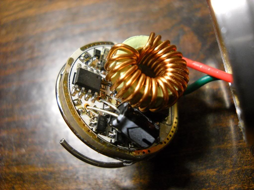
Just a couple picks of the driver. Good? Bad?
Anyone
Not sure about good or bad but definitely not the driver the originals came with originally. Perhaps they have changed the genuine driver since this light was first released? Perhaps this is not a genuine TR-3T6? My guess is the latter and not the former.
How does it perform for you? Any tailcap readings?
original driver.
High 2.01 a
Med 1.03 a
Low 0.23 a
with a set of trustfire flames
has some mildly noticable pwm on the low mode but not terrrible
just wondering if possibly I’m missing out on full potential of the light
Mine is about a year and a half old (got the 2 cell version from Manifont) Measures 2.6 amps with Xtar 18700's installed.
Not 100% sure by looking at your pictures. But it looks like the one I got with my wallbuys light, which was good.
Pictures, modifying and testing in this thread.
Ahhh…my bad. I really should pay better attention but I’ll use the excuse that I’m not feeling all too well today. ![]()
Your numbers are similar to what I had with my TR-3T6 using 3 cells. That driver was easy to mod by adding a resistor which bumped mine up from 1.8A to 2.4A at the tail. Not so sure what can be done to this driver.
Right on the money……thats the one. Sweet I think will try that resistor mod and bump the output. I have some srctic alumina coming maybe I will re-seat the emitters and look at possibly upgrading the wire size if needed.
Thanks
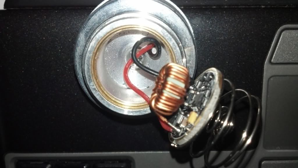
My driver looks different. It is the same one as Gary posted in RacerR86's thread here (post #24). I am only getting 1.7A on high with either TF flames or AW 18650's. I would like to also do the resistor mod, but don't know how since the driver is different than described above.
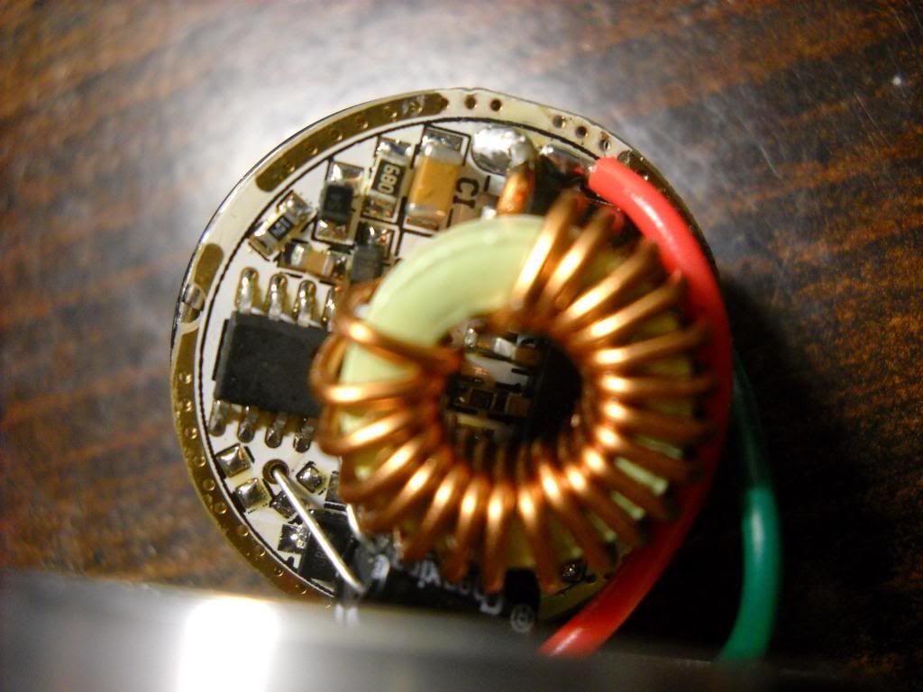
Follow instructions in image and I (or someone else who gets back to this faster) can help you wish resistor mod…
PPtk

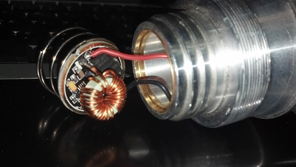
For me these drivers seem to be the same, just with a different form factor. So you have only one current sensing resistor instead of two parallel ones.
Make some pictures of everything like pilotptk has said.
And if you have a caliper please measure the diameter of your driver, just because I am curious…
Thanks you two!
I will post more detailed images of the driver tonight.
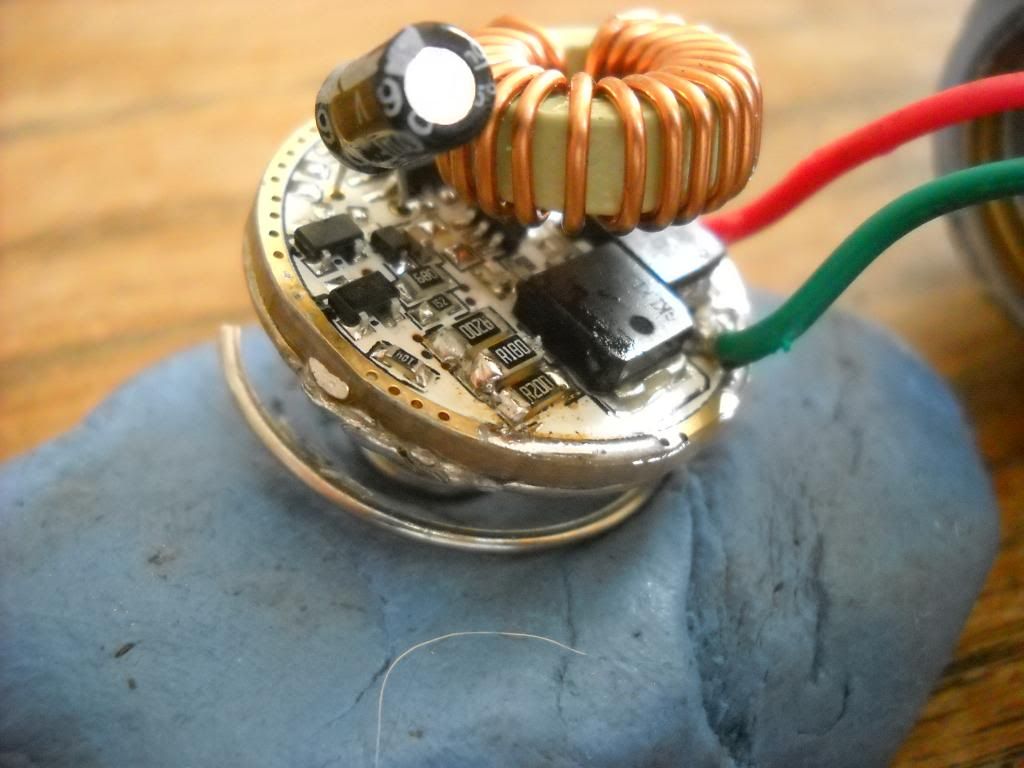
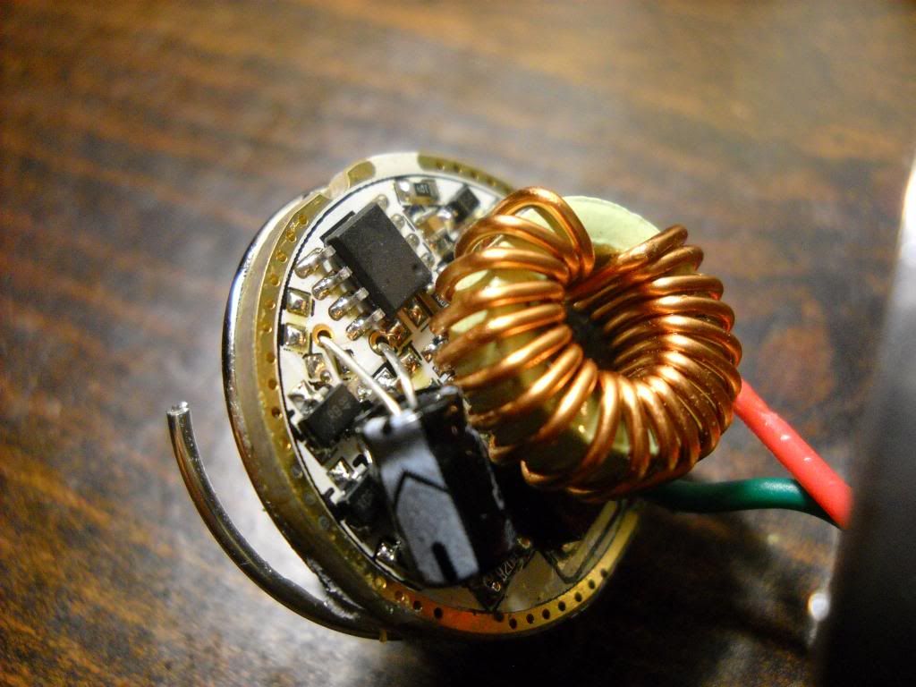
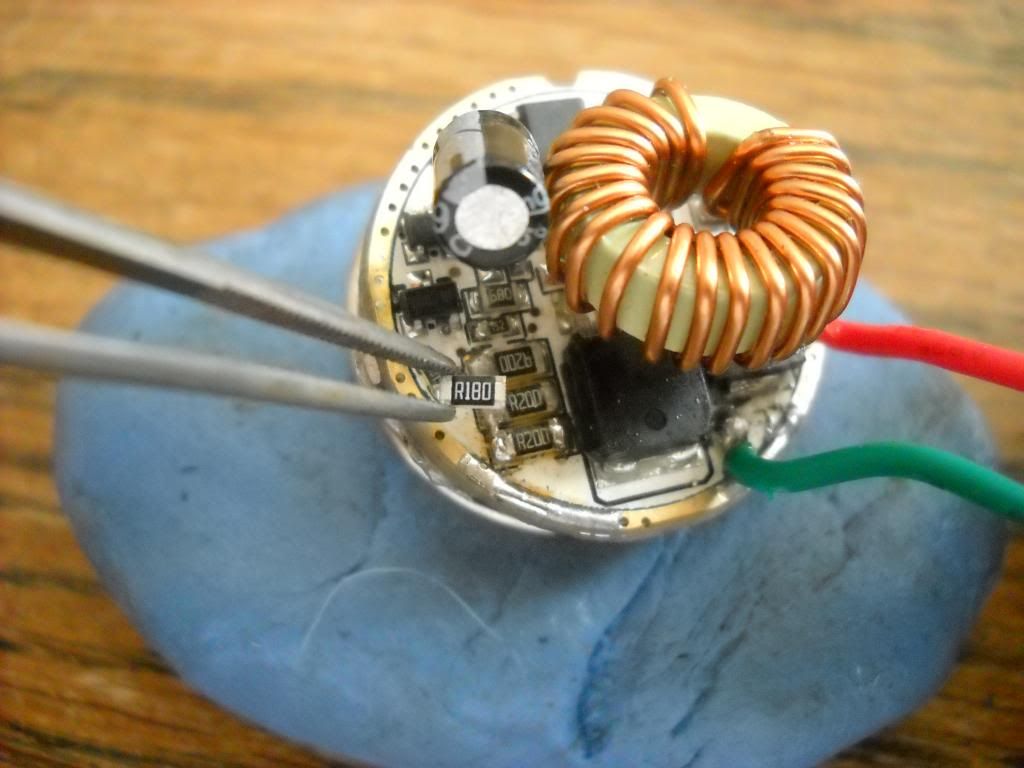
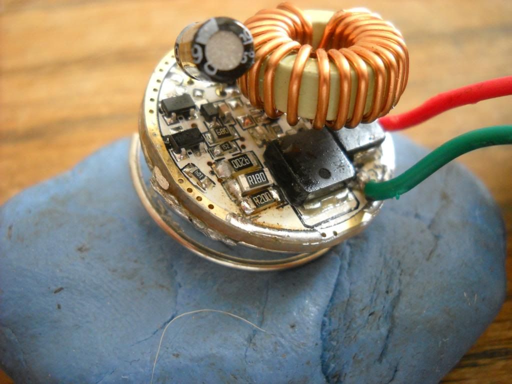
Photos of my TR 3T6 driver showing sense resistors under the capacitor. Inductor was also bent upward to better show components underneath.
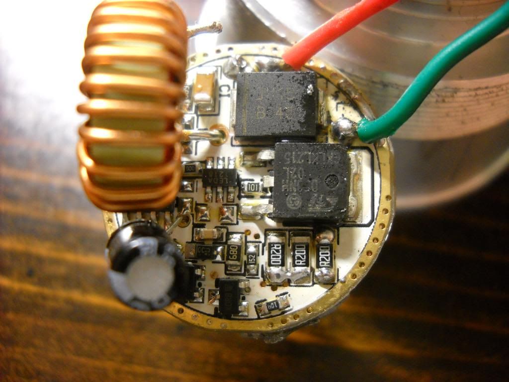
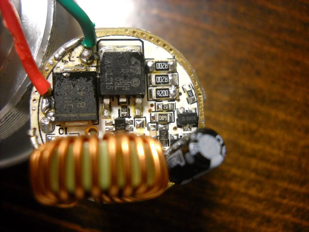
There you go, those R200 (0.2 Ohm = 200 milliOhm) resistors are the current set resistors. They look to be in parallel, so the actual current-set resistance is 66.6 milliOhms.
if 66.6 milliOhms equates to 1.7 Amps then, for 3 Amps…
( 1.7 * 66.6) / 3 = 37.4 milliOhms
Personally, I’d get two more 0.2 Ohm (R200) Resistors and solder them on top of two out of the three that are already there. That would put you at 40 milliOhms which should equate to about…
(1.7 * 66.6) / 40 = 2.83 Amps
http://www.fasttech.com/products/0/10003143/1234404-0805-02r-smd-precision-resistors-100-piece
http://www.mouser.com/ProductDetail/Bourns/CRL0805-FW-R200ELF/?qs=sGAEpiMZZMtlubZbdhIBINcPr0mSX6jr1ajheBtOXjg%3D
PPtk
P.S. I make no warranty, neither expressed nor implied, as to the suitability of the components on that driver to handle the increased current. They may work just fine, they may run hot, or they may explode off of the circuit board and melt a hole all the way to the center of the earth while vaporizing our atmosphere on the way down.
I could follow these conversations and know what was going on.
Lots of reading and learning and experimenting and blowing things up, and some day, you’ll be able to. I promise. Nothing horrendously complicated here - you just need to start from the beginning…
PPtk
Thanks very much for solving this. I am willing to take that chance and add the additional resistors for increased output. I may have some laying around here. Will report back when done!
And if you do the mod, think of the batteries these will see serious current which increases with depleting…so get some good batteries
The first board probably works the same but a lot of components are totally different. I think I will leave it alone though. It’s plenty bright enough for me at this point in time….maybe further down the road I will change it all around on the racer86 thread linked here whys the resistor green bodied? Never seen that before
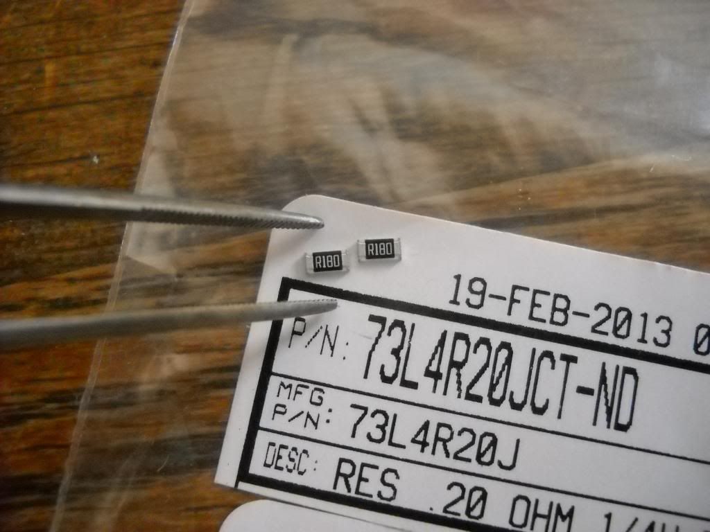
Ok, I did the resistor mod as suggested by PilotPTK above. I ended up using slightly lower values (18 instead of 20 milli-ohm)
I checked the current draw and lux (ceiling bounce) after adding one and two 0.18 ohm resistors in parallel to stock sense resistors. Here are the results:
No. of 18 milli ohm resistors |
Tail cap current w/2x18650 TF flames |
Ceiling bounce lux |
0 |
1.7A |
59 |
1 |
2.7A |
72 |
2 |
3.2A |
90 |
Overall, I am very happy with the results. Current draw increased from 1.7A (stock) to 3.2A. Output increased from 59 to 90 lux by ceiling bounce. Not bad for < $1.
Here are some photos of the mod in process. Before resistor mod. Three parallel 20 ohm resistors (R200).
Aligning first one on top of the center sense resistor. These suckers are really small!
In place and ready for heat.
One done! I didn't have enough hands to capture the soldering. I also did not take a picture of the second one, but it looks pretty much the same.