Thanks WarHawk-AVG!
Cool! I’ll check them out! Thanks DayLighter!
One difficulty with p60’s is getting a solder bridge from the driver to the edge of the brass pill. Before you install either the emitter or the driver it helps to pretin a spot on the pill with solder. Easier to muck around with this step when you don’t have to worry about the expensive parts. There are a few other ways so I’d advise learning a bit about this step before diving in.
Thanks Rufusbduck! I’ll pretin a spot on the pill.
I received the parts! Will post soon with pics.
![]()
Make sure you clean the spot well first with degreaser, sand it lightly with 400 or better w/d paper, and use flux(liquid flux works but paste is better) and plenty of heat. Even if it looks clean it will still have skin oil, manufacturing lubricant, or other contaminants that will foil your attempts to apply solder. The heat is the reason I like to pre tin. The solder needs to be wetted to the pill and it takes more heat to wet the solder to the pill than it takes to remelt solder already there. Properly wetted it will look like a coating rather than a blob sitting on the surface. Once you’ve done it a bunch of times you will develope your own preferences but it sucks messing up the driver on the first attempt.
Thanks for the tips! Will do! ![]()
Hey guys,
Sorry for this stupid question.
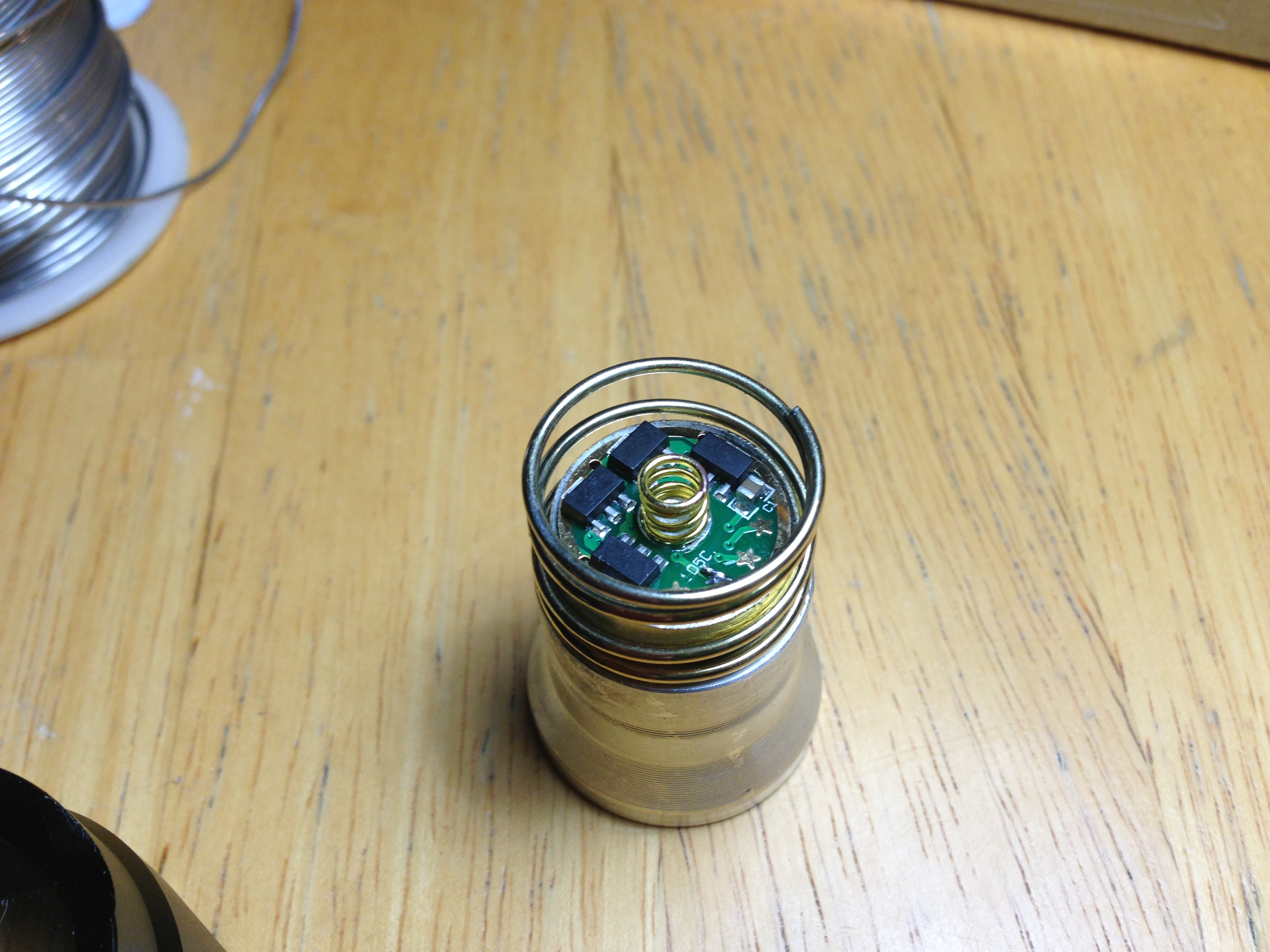
I got everything fitted, and I am trying to get the QLite Rev.A 7135*8 3.04A LED driver board ready.
It has four stars.
1st Star : 2% - 25% - 100% (Default)
2nd Star : 5% - 30% - 100% - Strobe - Beacon
3rd Star : 15% - 100%
4th Star : 5mA - 2% - 25% - 100%
I want to pick the 2nd star, but I don’t know which star is the 2nd one.
Here is a pic:
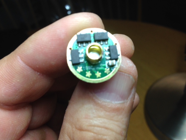
Is the 1st star on the left or is the 1st star on the right?
I know, I know… it’s a newbie question…
Looking at it just like that
L>R
1,2,3,4
Best way to jumper them is take a single strand of copper from a stranded wire, use it to jump the gap, otherwise the blob w/o something to bond to gets ugly quick (ask me how I know ![]() )
)
What he said about all of it.
Thanks! I figure I better make sure by asking you guys first. I don’t want to solder and unsolder mistakes. ![]()
You're just setting a logic level. I've been using a pencil mark to select the mode group on a few lights and haven't had any problems. Much easier to do and change, just erase and redraw to a different star. Simple to do even in the field, try that with solder.
I’ll have to try that next time. I shoulda read your post before I worked on it tonight. Many thanks for the tip. I’ll remember it for my next mod. ![]()
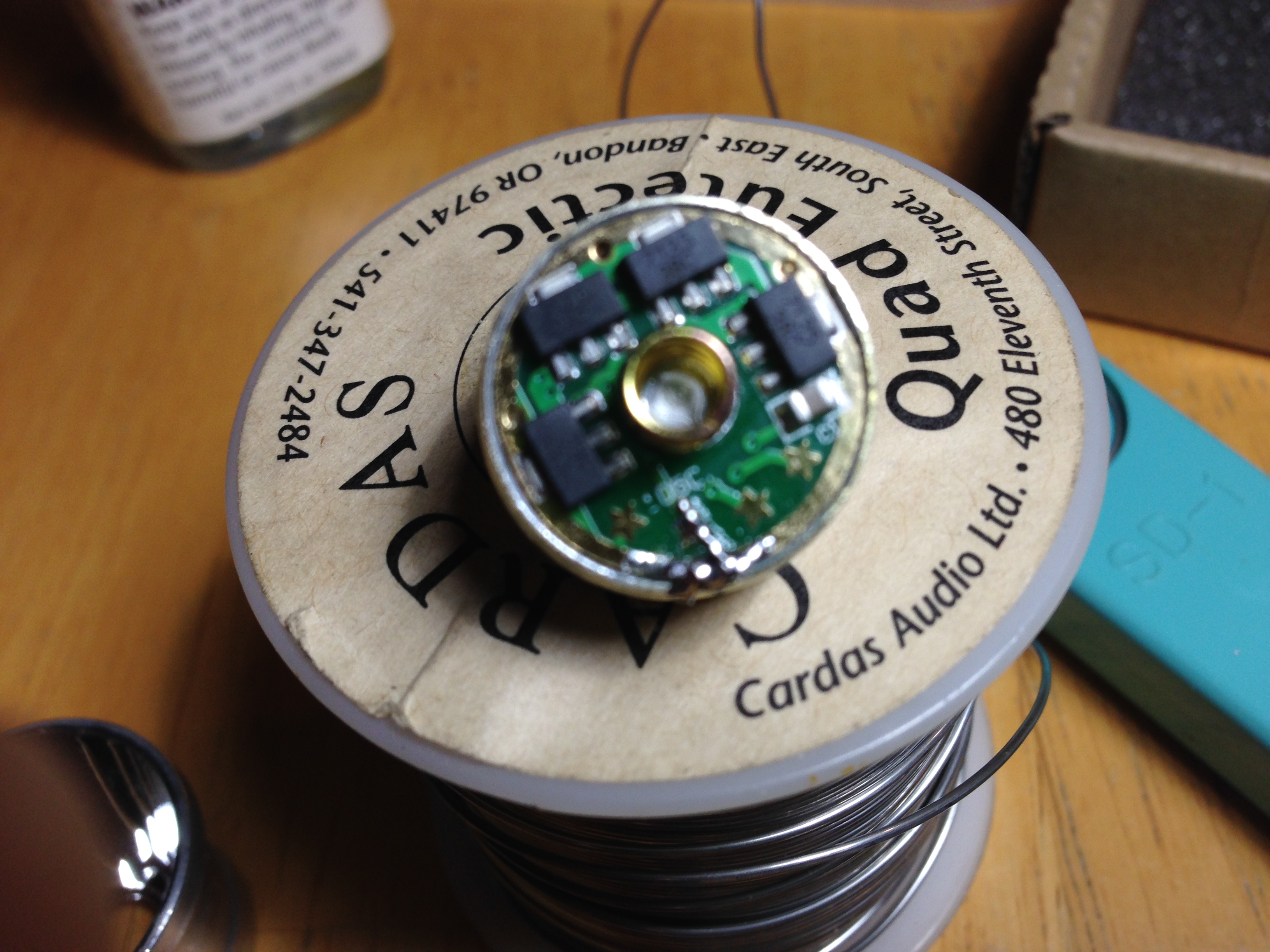
Ok. This post is picture heavy.
I soldered a small wire between star 2 and the ground ring to get mode L-M-H-F-B
I soldered the wires for the emitter
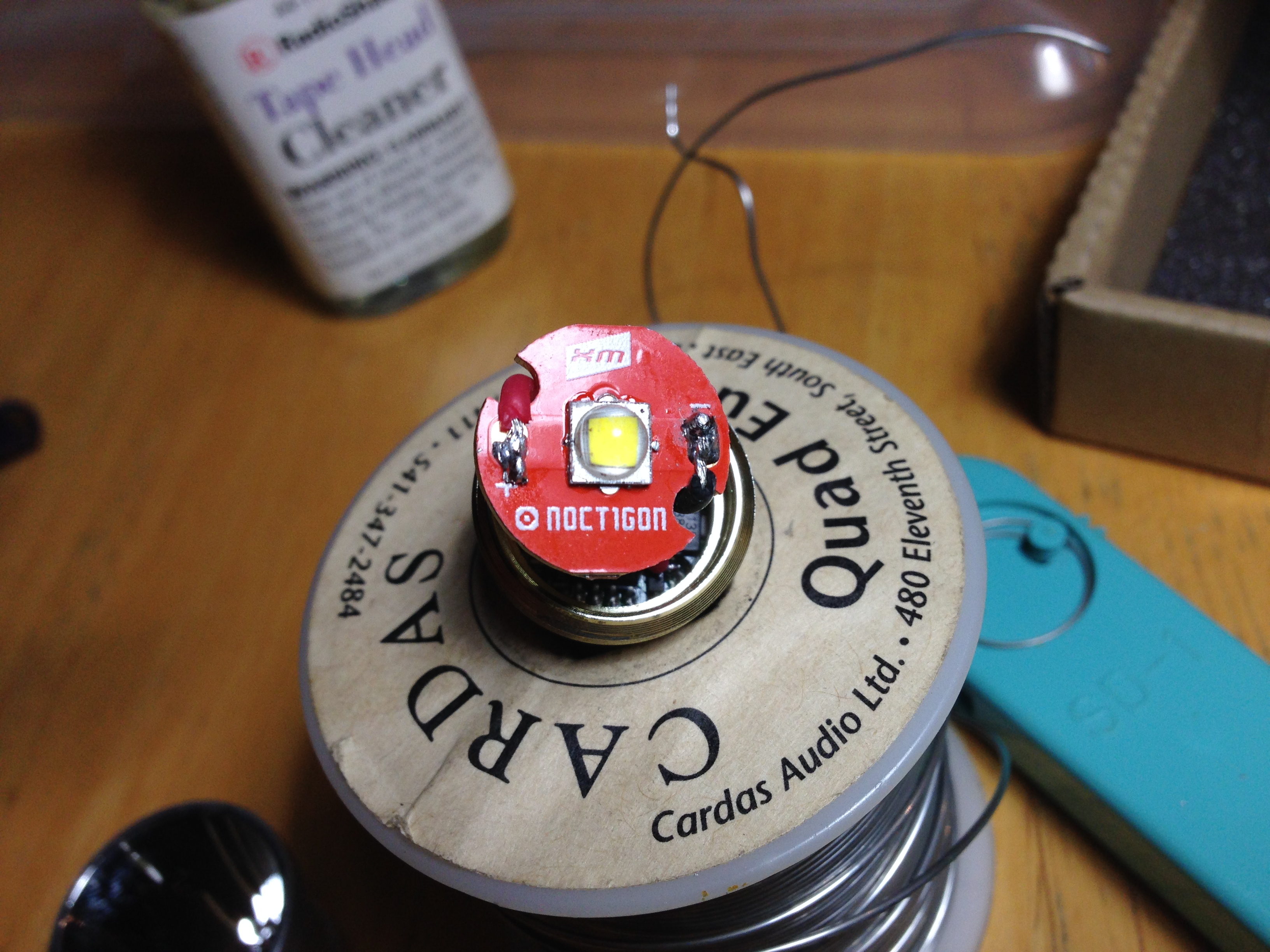
I covered it with an insulator
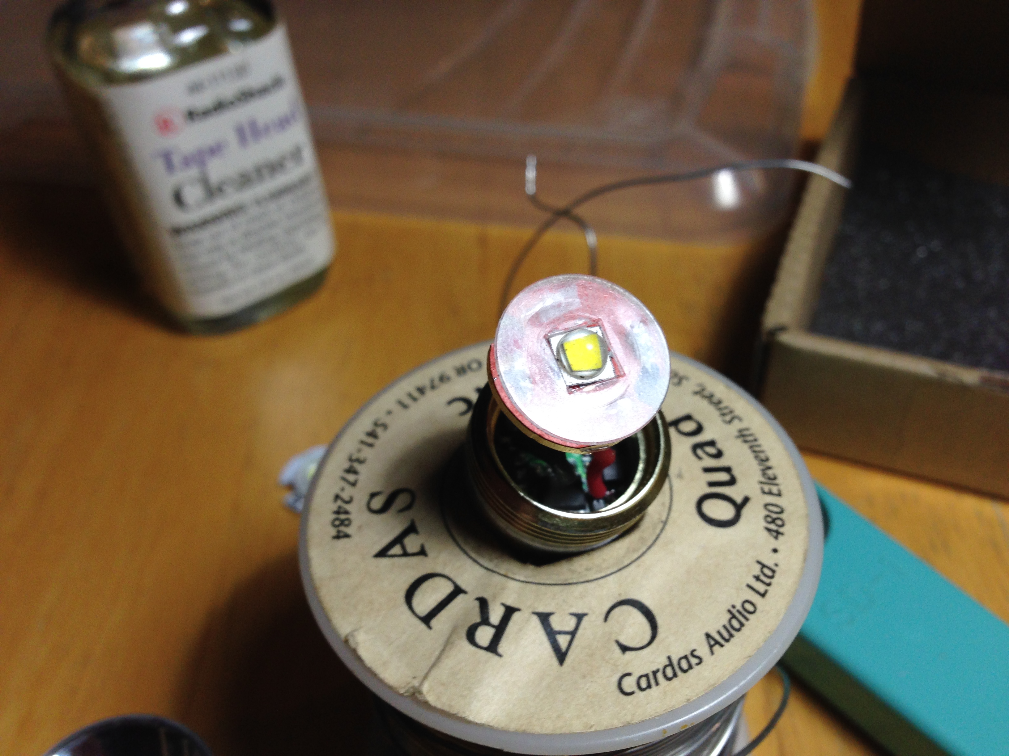
The battery was too short so I took the spring off the old driver board
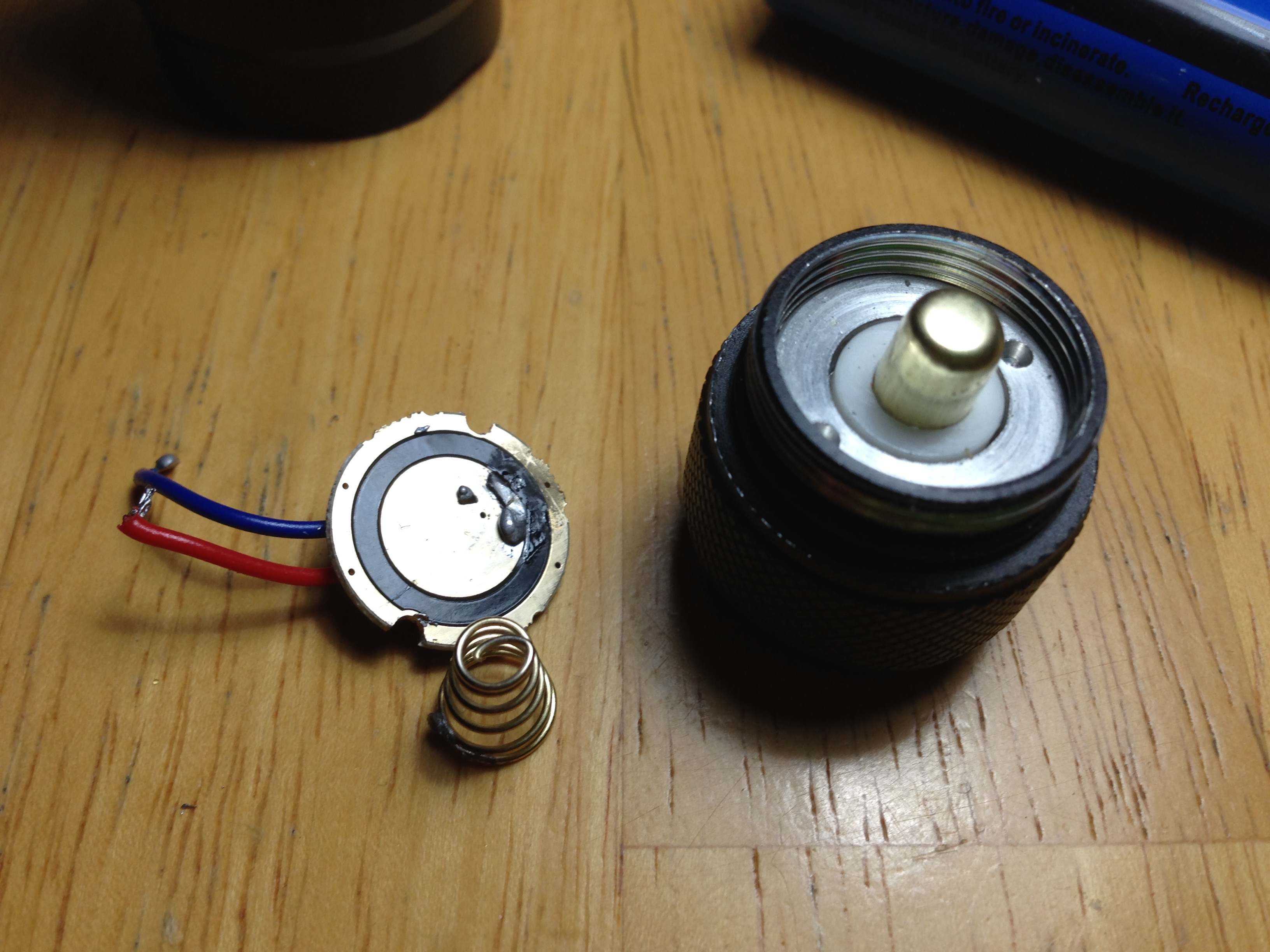
and stuck it on the brass post on the tail switch
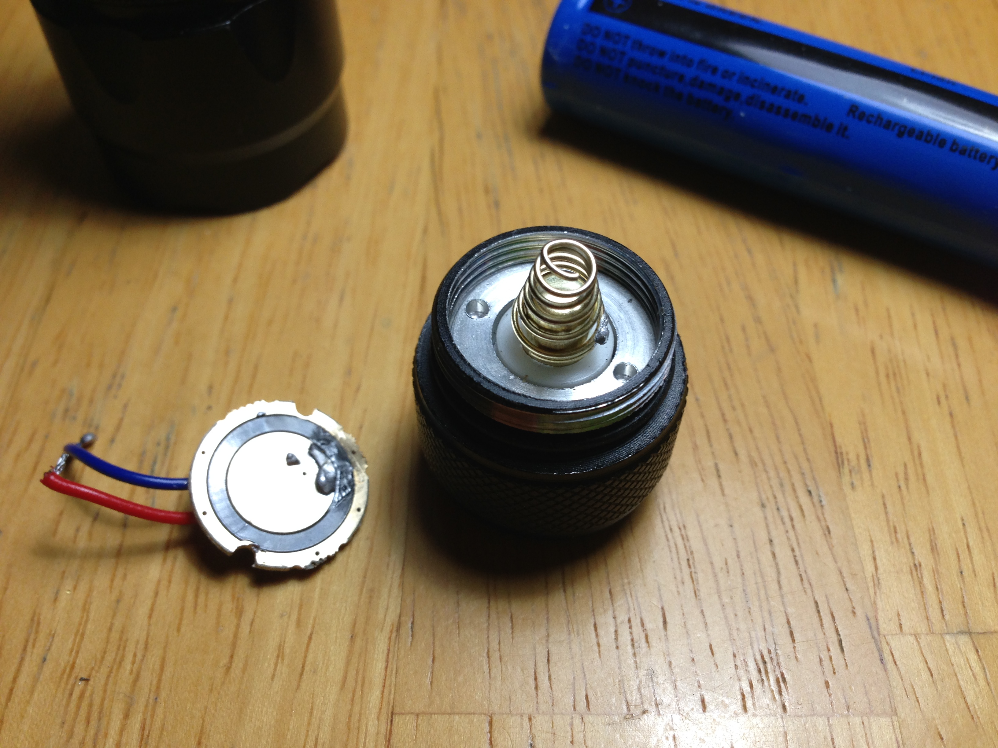
Here are the components assembled
Next post I will put a movie with me going thru the modes.
Hmmmm…… can’t figure out how to do movies. Anyways if you click on the text below it will prompt you to download the video.
Now here’s my problem. I can click between modes however it never stays on one mode.
For example, if I click it and set it on high or medium, after a few seconds, it will go into low mode. It never drops down to low when on flashing or beacon.
I thought it might be the spring, but when I short the negative on the battery to the case with a piece of solid metal, it still drops down to low mode.
Thanks for everyone’s tips and ideas. I really appreciate it!
Battery needs charging?
Or, a poor contact somewhere can fool the driver into responding to a low battery condition. Were you able to solder the ground ring of the driver to the brass pill? You might need to swap the small spring on the driver for the one stacked in the tail cap, that should be a soldered connection. Remove the small driver spring and solder the larger one in its place small end on the board.
A lot of peopl remove the small driver spring and replace it with a larger conical spring that is installed upside down so the smaller end fits on the pad.
I tried to solder it, but the brass pill looks like it is yellow coated aluminum and not real brass. I might have to end up using some kind of conductive epoxy. But I’ll give it a try again. The battery is fully charged.
So…. I guess when every the driver detects low voltage it will drop down to low mode so the battery doesn’t drain completely…
bronze? It’s solderable, but it’s a larger chunk of material so more heat is needed (use plenty of flux too)