um…duh…click the thermal outline, properties…actually had to turn off thermals for the pads to be solid instead of the broken pattern
Thanks Halo…
Do you guys want the “status led”?
More or less going to be on all the time the board has 5vdc applied to it
Files updated with thermals off (no render, same as the above, just now instead of having to draw a trace over the thermal cutout area and having to name it, it removes the auto gap created by the thermal parameter)
Halo… is correct. Note that I’ve got thermals turned on and nothing “covered” in all the pictures I posted on page 2 (you may need to zoom in to see the thermals).
Make sure you’ve got your polygon named correctly (same net as the stuff you want hooked up to).
It’s weird, I unchecked the thermals on my Eagle (they were on originally, they are off now on the new design) and the spaces went away on the redraw with ratsnest, with the thermals on, the little gaps were there
I had used a “cheat” method and used a large wire and named it the name of the polygon pour to cover up the thermals…removed them too
You can squeeze the board size smaller if you leave the led off.
I see you already have the led placed between the ports so it wouldn’t save much space leaving it off. You culd leave it on and people always have the option to just not populate the led/resistor.
I don’t actually plan to build or use one of these, so the status LED is of no consequence to me. I’d throw in the kitchen sink if there was space on the PCB. Earlier I added a second status LED, just for flexibility of placement.
It doesn’t absolutely need thermals but its best to use them. Without thermals you can have issues. Parts heat unevenly when soldering, might get tombstoned components. Perhaps even cause more thermal stress leading to a higher chance of failure. Ceramic capacitors don’t like stress.
The thermal connections are so short they only add a very tiny amount of resistance here. 3 or 4 thermal connections 0.254mm long, 0.45mm wide.
Ok, I will correct, and put the status LED back on
I have the above revision already inbound…so future purchases will have them
Also have the parts inbound…definitely want to test out current draw capabilities of devices thru the DCP…so far none of my devices will pull over 1A thru the charge doctor…I also have 3-5’ long cords so the losses in the cords could be rather large
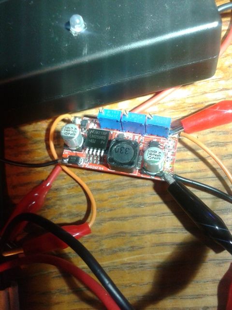
I set regulation for 5vdc (screwed up and forgot to up the max current, couldn’t figure out why I wasn’t getting more than 70mA thru it…duh, went back shorted output leads thru ammeter on multimeter, set for max of 2.5A)
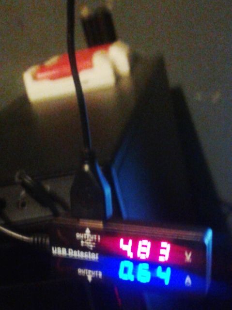
Here is charge into my phone straight out of front of computer thru the charge doctor (data enabled)
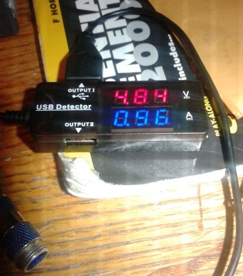
here is thru the DCP enumerator (data pins connected to the enumerator chip setting charge levels)
I don’t have a high current iphone or iPad to charge so I don’t know if it will push the max 10w or 2A out
but I did see marked improvement over regular downstream USB charging ports…I however think that it would just be easier for most applications to just provide resistor pads and solder a 100Ω resistor shorting the D+ and D- pins and setting it for 1A, would be cheaper and most devices can’t pull 2A for charging…will still test, maybe my daughters tablet will be able to pull 2A
Sorry for the crappy cell phone pics (oh and the box w/ LED behind the DC-DC regulator is my desulphator rocking away desulphating my motorcycle battery [in case you were wondering] also a test [the 13.5 should be 13.4vdc (float voltage, the desulphator uses about .33-.35A so the rest is slowly charging the battery, it started at approx .36A so it seems to be increasing the charge going in…maybe it’s working!])
Not being an electronics DIY type any more I bought the 5 smart port 40 watt AC input USB charger that Anker offers. Listed as capable of providing up to 2.4 Amps per port up to 40 Watts split between the 5 output ports as at least one Apple device can now take up to 2.4 Amps from a USB port while charging.