@khas: that is a really cool mod for that Blitzwolff. I may want to do that with mine.
Where did you get the 4000K 80CRI XHP35 Hi?
This also.
I presume its not 7135 based because I doubt those would be able to do 7000+ lumens. On other hand FET+1 that I tested does not work nicely with code I had, on the level where 7135 based driver is in stand by (no light), FET+1 produces some light, not sure about Anduril, maybe this code can switch off FET-1 driver without clicky switch.
So, my conclusion is that DBC is using FET only drivers, one with MCU and 2 more without MCU because 3 LEDs…
Would like to see that build thread ![]()
Guys, one more question:
I was preparing some parts for my Courui D01 and found this board from Mattaus in my parts list, at first glance it looked just like NANJG driver but with more 7135 regulators so I transplanted parts from NANJG 105C and add some regulators up to 20 of them in total.
Here are top and bottom pics from OL for reference
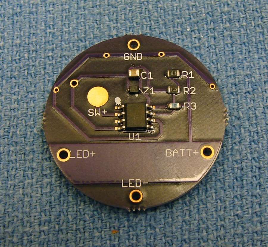
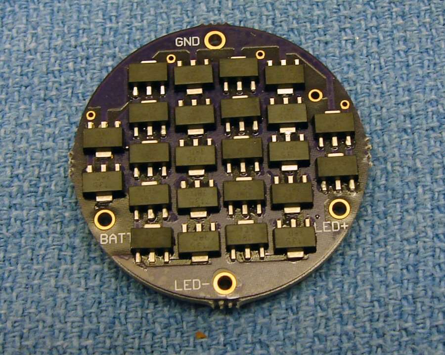
but there was not R3 on genuine NANJG driver so I was a bit suspicious and then find out that this is actually 6V MTG2 intended driver and I need it for XPL!
so I just left out R3 and Instead of zener diode I just used regular diode from NANJG driver.
I hope it will work ![]() because I don’t have other/better solution for eswitch only.
because I don’t have other/better solution for eswitch only.
Hi mate! Thanks for your answers! So, a simple replacement from the reflector to the optic is not happening due to the internal height, right?
You had to cut it on the sides or on the legs?
About this question - Did you pick the stock wires or did you put new ones? - what I meant was if you used the stock wires from the driver or did you have to/managed to put new ones (maybe thicker?) for the triple board! ![]()
Thanks for the explanations in advance and…I know, to get a nice photo from these lights with such a dim luminosity…it’s pain ![]() But that’s what make these lights awesome
But that’s what make these lights awesome ![]()
Good work!!
I’ll take a stab at this too…
I don’t see an advantage to using three FETs because one is enough. I have a triple SST-40 that pulls just over 24 amps through a single FET. DBC’s lights for sure pull more than that. The 7350 lumens is probably measured on full on boost/turbo mode with a single FET. I’m guessing the slave boards are 7135 only so the lower modes can be fully regulated with higher output. If you have 16 x 7135s you can have 5.6 amps without activating the FET.
Just guessing though! DBC will surely set us all straight soon enough ![]()
Wait what? 24A fet driver, when did that happen ![]()
I need one of those, where do I go to buy ![]()
In most cases it’s not the FET that is the limiting factor, it’s the cells, wires, LEDs and so on. My 24 amps, although through a single FET (same as many others use), is from three cells: Mod: Olight SR Mini with triple SST-40 and host bypass.
Found the led on KD ![]()
Any idea about the output? (guess 1700)
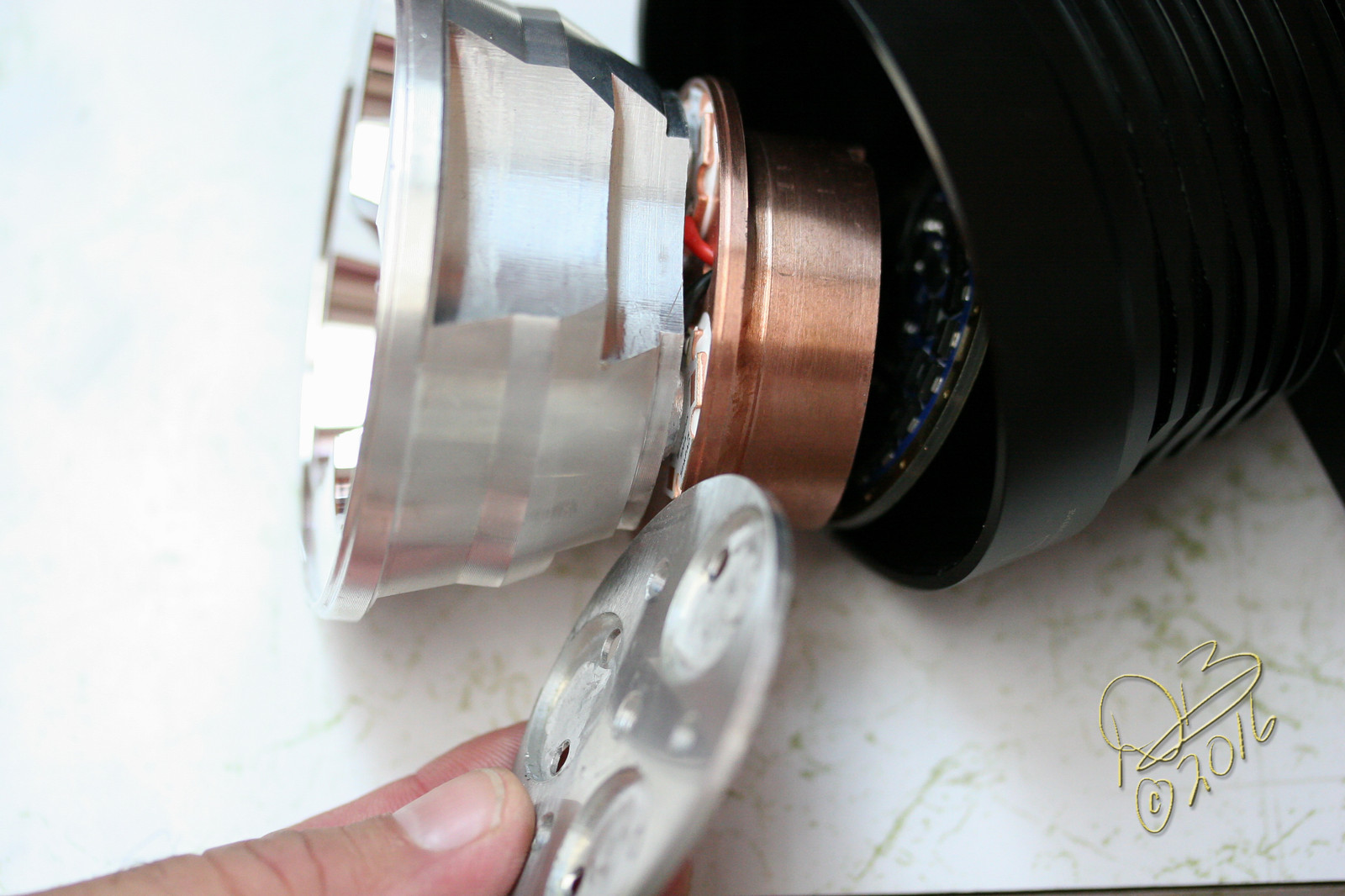
No it’s not a simple swapping out of reflector and optic. There is a spacer behind the led board, the led board has been cut down and the optic has been cut down. The sides of the legs and sides of the optics have been cut back. This pic below gives an idea, stock one left, the cut one right.
I don’t have a pic of it but the driver is 2 boards sandwiched together. The led wire solder points are in between the two boards so all I did was extend the existing wires to reach through the spacer to the led baord. I’m not worried about using thicker wire as the driver still puts out the same power.

I used a 17mm FET+1 driver flashed with Anduril as the Master unit and 2 standard FET driver boards housing only an FET for the 2 slaves. To operate the 2 slave units I ran a wire from pin 6 of the MCU to tell the FET when to turn on. What I didn’t think about was that the FET+1 is a 2 channel driver, in the lower modes below the 380mAh of the 7135 chip this chip is operating alone, no input from the FET, so my 2 slave units only turn on when that level is surpassed. This results in the light working on a single LED in the lower levels and all 3 above that step.
On the one hand, this makes the light more energy efficient at the lower levels running one emitter on one 7135, but on the other hand my OCD doesn’t like 1 of 3 working like this, it doesn’t look right. lol
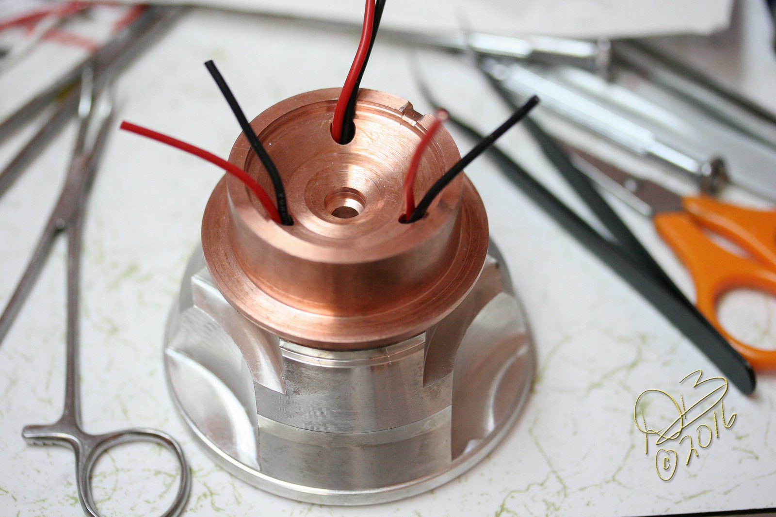
To run positive to the slaves I ran 2 pieces of solid wire 12ga Romex between the Master and Slaves, then ran a single 18ga lead up to the emitters and tied it, unbroken, to all 3 emitters. Each negative lead to the emitters comes from the separate boards.
I knew that the SST-40 is capable of pulling a lot of amperage individually so I wanted to try attaining high levels to each one with the 4 18650 power supply. Looks like my average is around 2450 lumens per emitter so it’s working out pretty well.
PS: I should also mention that I built this light originally several years ago. I upgraded it with a very large Tellurium/Copper heat sink and had it running 3 de-domed XM-L2 emitters. I had originally used Richards (MTNElectronics) 7135 based SRK driver with additional 7135 chips to make a total count of 41.
I had sold this one here back when I got caught in the VW Diesel scandal and had 2 car payments while waiting for VW to buy back my Sportwagon TDi. The owner contacted me recently about modifying it or possibly buying it back and I bought it back. To do this mod I had to remove some more stock inside the heavy copper heat sink for the “bus bar” style rails to clear (the positive supply between the drivers)
I wouldn’t have done the SST-40 mod without this much more efficient heat sink, the original mounting plate is ridiculously thin.
I built it up like this back in March of 2016. ![]()

In looking for the above pics I ran across this build to a Raysoon F13, baked, that I also did around the same time… Spring of 2016. Anyone spot the oddity in this one? ![]()
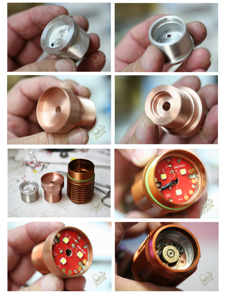
Nice battery contact. Not sure if manufacturers will use that idea… :laughing:
My guess would be 1600 OTF lumens.
I didn’t take any photos of the mod, but the tail switch is a bit strange. It look a bit like the one in the picture in a threaded aluminium housing that screws in the tail. I ended up with sanding the housing down and using it as a retaining ring for a normal tail switch board.

If flying/traveling with that light it would be best to check that light with bags, than bring as carry-on :zipper_mouth_face:
Good thing the primer is spent…. ![]()
Quick question especially for DBCustom, CRX, and any machinists in BLF.
Do you guys have any idea how to lap (not milling) a one piece LED shelf in a flashlight perfectly flat with off the shelf tool?
I’m using a rotary table (offset circular motion) and custom made cast iron lapping disc (used slurry SiC pasta). The results has been good so far, but’s it leaves mess on the milling table. Just curious if there’s a factory made device for it.
Thanks,
Clemence
Sorry Clemence, don’t know… I don’t lap the shelves on mine. If I were planning on using Gallium between a copper heat sink and a copper MCPCB I MIGHT go that far, but typically I just let the thermal paste cover the irregularities.
Haven’t seen many built in shelfs as I usually deal with the smaller lights and don’t bother too much unless there’s a real bump in the centre or such. A proper sized flat round fine grinding wheel has been used before, ones with no centre hole.
I did a quick search, was surprised nothing really applicable came up, these things prob have proper names…
clemence
What material do you work with?
Thanks guys, it’s just my thing to have a perfectly flat almost mirror like base ![]() .
.
CRX, those usually called grinding cup. I'll try the diamond version. Kiriba, mostly just unknown cast aluminum, 2024 Al, and for special case common copper.
- Clemence
Fine grit sandpaper and a granite flat stone will work well.