I think, yes, but we will have to wait until my xhp50.2 arrive and see
Today i did yet another led swap in my Convoy M1, this time sliced XP-L2 V6 5000k led. It makes about 1500 lumens and 28500cd. To be honest i expected a bit more.
At least the beam is very nice, no green hue around the hotspot at all.


How much current is it getting?
How did you dedome it so cleanly?
A lot of current, 8.5A with VTC6 and a bit more with 25R. The led it is not fully dedomed, the dome is sliced of the led as close as possible to the die and also i scraped the phospor that was surrounding the die, all i used was just a sharp knife.
Swapped the driver in my Jaxman E2L for a DrJones H17F.
I tried swapping the star too, but that sucker is royally glued in. I think to get the star out I’ll need to drill a hole through the shelf and then use a hammer and chisel. That will reduce the available shelf-space, but is probably the only way to get it out. If I try that hopefully the tube near the bezel won’t collapse while I’m hammering.
I was not impressed with how the light performed with the FET driver. The head would get burning hot in seconds. And the H17F’s temperature regulation wasn’t kicking in fast enough. Even with AS5 thermal grease over part of the driver it still got way too hot.
This is the disadvantage of pill-less tube lights. They’re better at getting heat out of the LED than having a pill…. but that doesn’t help much if because of the lack of pill they get dangerously hot in seconds.
I can run this light at the second highest possible setting on the H17F driver without having it get too hot. (2nd FET setting). Output will dim quickly as temp regulation kicks in. However, this is still better than my cut-down S2+ which requires me to have turbo set at the 3rd highest setting (3 amps).
If you care to use the stock MCPCB of your E2L, you could try to reflow new leds with the MCPCB in place, by heating the complete head, at least that is how I did it. I had rather have the board out to make sure it was flat on the shelf with a thin layer of AS5 in between instead of an unknown gooey of unknown thickness, but as you say, there was no way to get the board out.
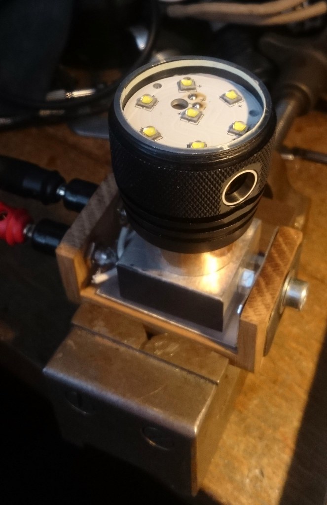
Today I swapped the 7 XP-G2 leds of my DQG26650tiny for Nichia 219C 3500K R9050 leds, and in the process managed to screw up the switch cover.
Ok, someone before me probably has taken the switch cover out as well, and found as well as me that no one in the world will get it back in, and probably even posted about it. But I managed to miss that. That ss ring around the switch appears press-fitting the rim of the switch cover and that is a one-way thing, once you pull out the cover it will not go back in the groove, And that ring will not move, may be glued as well. I finally got the cover in position without the rim in the groove, and by placing a steel ring (bottom ring clipped off a spring) behind it on the inside, which is held in place against the edge of the driver, all functions well. But I don’t think it will keep the water out if the light would get submerged. Rain should be fine.
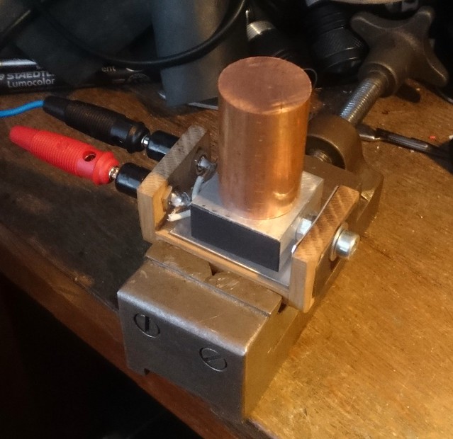
Originally I planned to swap the leds with my new hot air reflow machine, but I wanted to have some experience with it before trying this 7-led swap. So I decided to postpone the hot air method and go for the hotplate method, with the gutted DQG head on top of a chunknof copper. Had to fire up the heatblock to 275degC to get the reflow done.
The beam is great, the tint can’t be better, it is just a pity that the switch cover never got back properly ![]()
Was it not possible to get the MCPCB out, without removing the driver and switch cover?
I did not even try that, I must admit, after DBcustom’s report of failing to get it out. I could have had a go at it if I thought about it.
Thermal transfer foam might help, if you can fit some directly between the MCU and the back side of the MCPCB shelf. I finally got some and plan on trying it out soon while I make some new thermal regulation code. In theory, it should allow the driver to respond faster and more accurately compared to having an air gap between the MCU and the pill.
I should get some of that. It’s probably less messy and costly than trying to fill the area above the driver with AS5. :smiling_imp:
Now that Mountain Electronics has E2L hosts in, I ordered a couple. Better than trying to drill and hammer out the stock star. That white stuff they used to glue it down is STRONG!
Today flashed an S8 with Biscotti and added white lighted tailcap to it.
Thanks LightRider and Lexel, I got the H03 open pretty easily using your input. I put a FET-only driver in there with Toykeeper’s ramping FW. I only had a 20mm driver on hand while a 21mm is what is supposed to fit in there. Some strategically placed solder and copper around the edges made it fit well enough. I lifted up pin 6 on the MCU so it doesn’t contact the board and put a 270 ohm resistor between it and the FET gate in order to lower the lowest mode. That puts the moonlight mode around 0.3 lumens. I also bypassed the tailcap spring. I’m getting around 4 or 4.5A with a Sanyo GA cell at around 4.0V. Another thing I’ve been doing with the ramping FWs (this one and Crescendo) is put a “blink” in the ramp around 40% duty cycle just to give me a reference so I know roughly what the current draw is. I’m pretty pleased with it now.
That’s the one thing which bugs me about ramping. I never know how many lumens it’s making or how long the battery will last. It’s easier to gauge that with discrete levels.
But over time I’ve kinda stopped caring whether it’ll last 15 hours or 60 hours, as long as it’s long enough for whatever I’m doing. It’s not hard to recharge the battery a little more often if I need to… like every 2 months instead of every 3 months.
WOW 9.3 amps
Some days ago, I modded a Convoy BD02. Added some AMC7135 and changed the LED to XP-L2:
German: Convoy BD02 mit XP-L2 möglich? | Taschenlampen Forum
English by Google: https://translate.google.de/translate?hl=de&sl=de&tl=en&u=http%3A%2F%2Fwww.taschenlampen-forum.de%2Fthreads%2Fconvoy-bd02-mit-xp-l2-möglich.55467%2F
TK, that is awesome work! I have seen an old P60 that programmed that way, but I think it had a sensor as well. I am trying to build a tiny board to measure PWM the same way. Will feed an arduino the pulses and count them for display.
So, this is a few days old but I finally made something to show the general proof of concept.
First, LEDs are pretty decent light sensors. Here’s my DMM measuring brightness (ish) and PWM speed with a LED hooked up:

So I tried it with a flashlight, a BLF X5 prototype I had laying around. I connected pin3 to LED- and changed the firmware but otherwise it’s unmodified. Here’s a video showing the light reading data from a notebook screen. Specifically, what happens is:
- First I fast-press it a bunch of times to get into programming mode.
- Some diagnostic blinks; ignore that.
- Light buzzes to give the user time to skip the mode.
- Light calibrates light and dark levels from the screen.
- Light blinks out the ADC values it measured — 156 (bright) and 167 (dark).
- Light reads eight bytes in binary, one at a time, and blinks out their values in decimal: 247, 135, 84, 58, 31, 17, 6, 0. You can’t see it, but these values get stored in eeprom to configure a mode group.
- Light fast-blinks and exits programming mode.
It’s all intentionally slow for initial testing purposes, but should get a bit faster later. Not fast fast, maybe only the speed of a Morse telegraph, but still faster than what it shows in the video. (maximum speed is probably about 1 byte per second, mostly due to limitations of computer screen refresh rates)
Some pics showing the host a bit better:


TK, that is so cool! I would offer any assistance I could, but not being a hardcore coder like you I am afraid it would be limited. If you need other monitors tested, I could help you with that as I have several with different resolutions and refresh rates. I do have that driver inbound at the moment and can flash test code if needed.
In latest Narsil versions for ramping, I blink the indicator LED to show what channel you are on, at least. On triple channels, 1 blink for the one 7135, 2 for the bank, 3 for the FET. For Narsil 2 channel, 1 blink for the 7135, 2 blinks for the FET. At least you know what channel you are on, but yes, totally agree - this always troubled me as well.
TK - nice seeing this capability actually functioning. Hhmm - I really need to explore this as well...