My brightest direct drive SS-5039 10440 light is one that I made into a twisty. In many lights the switch is integral with the tail spring, or odd shaped, or small, and hard to replace with a lower resistance one. Also, for pocket lights, some length can be saved by cutting off the part that holds the switch. The most compact lights are all twisties.
Sorry for all the confusion guys; MRsDNF is spot on with what I’m trying to say.
Check out djozz’ in-depth post regarding spring resistance.
When building any high-Amp capable builds, such as your triple, a spring bypass becomes necessary, both to get the expected performance, & to stop the spring its self from overheating & collapsing.
Or replace with beryllium copper springs and you don't have to bypass anything.
I get bypassing the springs, I’m talking about drilling a hole through the PCB and running a wire directly from the spring to the switch.
You are connecting directly to the switch tab, rather than relying on the via of the PCB and it’s traces.
Again, its about minimising resistance.
Ahhh - ok. This mod , for me, came directly from Dale - he described it with pictures in great detail - where, I dunno, but I'm pretty sure it was on one of his triple or quad BLF EE A6's X6's. With the insane DD multi emitter single cell lights we build, there's a lot of amps going thru the tailcap, like 10A+. He said he had experiences where he smoked the trace on the PCB board the switch is mounted on, so the purpose of this bypass mod is to eliminate the use of the PCB trace that might burn up from the high amps.
So it's not a mod that was done to lower resistance, but rather to save the trace from burning up. I think it's side effect though is lowering resistance by a very small amount. From my experiences, the weakest (highest resistance) part of a circuit will be the failure point, so for the EE X6 lights, most likely that trace is the weak point in the tail.
I've done this mod on the two multi-LED EE X6 lights I built. I think I did it on a couple of other lights. It's very similar to the tailcap mods we do on the SupFire M6 or other SRK style lights where we bypass the PCB traces. I've done similar mods to the battery carriers in lights like the Shocker. Traces on PCB boards, specially long ones, can't compete with 22 or even 20 AWG wires.
post #156 & 165
Very nice indeed...
For lazy people video about how to is here
Picture is here.
Thanks to the author DBCstm
I once did this to bypass the ramping circuit in a tailcap… it made so much sense I do all my spring-bypassed tail switches like this.
Oops - yes Nitro, that's it! In your heat sink thread  . Oops - I typed A6 but meant X6 - corrected above... Dale (DBStrm) mentioned this mod a few times, never knew exactly what he was doing til he posted the pics and video. I'm thinking it helps lower resistance on high amp mods a little, maybe more than I first eluded to.
Can you suggest one please,good for a BLF A6,a Nitecore P12GT and a Cometa?I don’t put in the row the SR52-UT and the K70,because I am afraid if I ruin them,as their price is high enough.
I am more interested especially for the Nitecore,because when I swapped the mirror of the A6 to a 20mm 15 Degree Cree XM-L LED Lens,the Nitecore gone away ashamed,so I want to give it a “viagra”. 
Not sure I understand. By suggest one, do you mean a replacement switch? As far as I know, all the switch's in the lights you mention are better quality ones. I've only replaced cheap, poor performing switch's, typically more common in under $12 lights.
It’s all about resistance.
That is one of the cons putting high amps through a circuit.
You know about ohms law right? V / I = R
More Amps, with a fixed resistance, equals more power (watt) turned in to heat.
So the trace (or spring) is rated for ‘x’ Amps, i.e. has ‘y’ ohms resistance, when you put more than ‘x’ Amps trough the trace it heats up because the resistance stays the same i.e. more power is turned in to heat. That’s way it burns up.
When we lower the resistance, using a bypass, more current can flow maintaining the same power lost OR lowering the power lost and maintaining the same current.
In flashlights both happens, because the current is somewhat controlled by the battery, led and driver.
A theoretical example:
Using a voltage supply of 4.2V, led voltage threshold of 3V and total resistance of 0.1 ohm
I=V/R, I = current, V = voltage, R = resistance.
- 4.2V - 3V = 1.2V / 0.1 ohm = 12A.
That means there flows 12A trough the curcuit.
Power turned to heat in resistor is (P=VxI) 1.2V x 12 A = 14.4 W.
In this example we lower the resistor to 0.01 ohm
- we get 1.2V / 0.01 ohm = 120A.
Power turned in to heat in resistor is 1.2V x 120A = 144 W.
But the current is limited by a couple factors (voltage drop battery and voltage increase led)
So in this example we have a voltage supply of 3.8V and a led voltage threshold of 3.68V
- 3.8V - 3.68V = 0.12V / 0.01 = 12A
0.12V x 12A = 1.44W turned to heat in resistor.
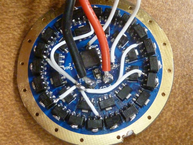
Hope this is not directed to me because lot of time wasted then. You realize the quoted piece of a post is from a year ago? I've been bypassing traces in mods for certainly over 2 years, maybe 3, and I've been criticized for doing too much of it. I thought I was one of the originals that did it, and still do it on a regular basis. Here's my 6 bypass's on a MtnE SRK driver, with 18 7135's added, and the bypass's gained about 2.5A:
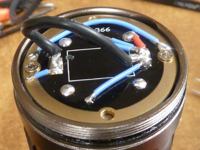
And these are bypass's on the tail of the same SRK clone with a heavy gauge clamp meter loop build in:
I agree with toms bypassing (beefing up) of traces. I followed his lead in bypassing all the traces in the battery carrier of my BTU shocker and gained a full 1A gain, which was pretty much the same gain Tom realized when he originally beefed up his Shocker traces. That’s confirmation enough for me.
Didn’t realize that, but it was not directly pointed to you. Though does sound like it.
Just some general info.
ΟΚ thanks.You see it is not enough time I am in the lights’ club.
Battery capacity is measured in amp hours but it’s the voltage supplied that generates the current. Eliminating resistance eliminates voltage drops so that it remains available to the led leading to higher current through the led at any given battery voltage.
Tom E,
A lot of effort in your work… Awesome 