New to the forum, but been a casual flashlight enthusiast for awhile. I’m an embedded software/hardware engineer by day, and thought I would share a new 20mm driver design I’ve been working on. This driver will hopefully have a feature I haven’t seen elsewhere, using the emitter itself as an ambient light sensor. Most people will probably not find this useful day-to-day, but there is one feature in particular it could be very useful for: wireless firmware updates. By exposing the emitter to a light source capable of modulation, new firmware versions can be programmed without wires. I’m envisioning a webpage with some javascript that flashes the screen black/white for a single bit. Admittedly at 10 bits/sec, it will take ~27min to upload 2KB, but that’s a problem for another day. Of course, firmware updates are a moot point if the driver has sub-par performance. My other main focus was to maximize the lumen-hours on a given battery. For me, efficiency gains are going to be most impactful when the light is between 100 and 500 lumens. However, I still want the ability to step up to 1500lm for short periods when needed.
For the past few weeks I have been converging on a closed loop constant current Buck-Boost regulator using Spice. As with any design, there will always be some tweaks, but I’m pretty certain the general architecture of the design is going to work. While I’m mainly targeting this driver for a single emitter, there were a few reasons (which I won’t get into now) why I decided to go with a buck-boost topology. Here are the design requirements I settled on:
Design Needs
5A turbo
High efficiency at sustained output
No PWM in any modes
True moonlight mode (<50uA)
Constant output regardless of battery voltage
Emitter as ambient light sensor
Low battery detection/protection
Design Wants
firmware update using ALS?
thermal regulation
Tint shifting (psuedo-PWM)
6V, 9V and 12V capable
Low quiescent current draw
Sub-step dithering
Design Freebies
FRAM memory, never wears out unlike EEPROMs
2 layer, single-sided pcb layout
No gaps in entire output range
The main buck boost converter is a relatively new offering from Texas Instruments, TPS55289. It greatly simplifies the feedback loop thanks to its ability to regulate the output current without an external current sense amp. It also has decent power handling capability for the size. I’m going with a MSP430FR23xx series MCU because it has everything I need, and nothing more: I2C peripheral, integrated opamp and TIA, and FRAM to boot (no EEPROM needed). For now, I’m going to try out a 20mm version to see how well theory translates to reality, but it’s probably possible to shrink it down to 17mm with a 4 layer / double sided PCB.
Anyway, I’d really appreciate if I could get everyone’s .02, especially other HW/FW developers. Would anyone else other than myself value wireless FW updates, or would is it too gimmicky? Any other hardware features you’d like to see? Since I am not going with an Attiny and stubborn, I will be writing the firmware from scratch, most likely Anduril-esque with my own twist. Hopefully I’m not steping on any toes by duplicating another dev’s UI. I also have not tried not considered component cost at all, which may be an issue if I ever decide to make a batch of these.
Must have missed that, and I even have a FW3A haha.
It seems like the main hurdle is finding a light modulation source that has a fast enough data rate to make it a viable option. I could see it being used by the end user if total programming time is 5-10 minutes. Again, it may be that there is no easy and fast way to do this.
I’d also like to explore how well it functions as an ambient light sensor in dark situations. The builtin transimpedance amp comes in handy when measuring uA or nA levels. In theory, you could turn the led off for a few milliseconds, take a reading, then turn back on. If the buck-boost regulator can turn on/off fast enough, measurement events may not be visible.
I can’t help with the original question but I mentioned this a few years ago in a thread as a feature I would love in a future driver - I wonder if it would be easier to create a pcb based wifi antenna (the square-wave looking design) and offer PC-configurable firmware to flash it with? I would love a computer or phone based interface that allows you to tick or un-tick the number of modes, memory on or off, strobe or no strobe, where in the order you wanted the strobe etc and then the program compiles it and then writes it to your driver wirelessly with wi-fi or nfc. Asking way too much? Most likely! But one can dream.
I’ve noticed lots of emitters stay very dimly lit after turning then off for a surprising amount of time (sometimes a second or two). Do you know if this is due to the driver or the emitter? It may interfere with your non visible light measuring. Other than that the driver sounds very intetesting
I would go for USB Firmware Updates over wireless. flashlight bodies are usually full aluminum, not much signal will get in or out, and antennas for 2.4 GHz are not super small. And unless you use a ESP32-ish chip that hosts a webserver which you connect to and then upload new FW, it also needs special software again (like the Adafruit BLE OTA firmware update thing for their nRF528xx bootloader).
USB updates via ideally uf2 are the most user-friendly choice IMO. No drivers or tools needed on any hardware/OS (android, iOS, macOS, windows, linux) since it uses mass storage protocol. DFU being the second choice, it needs apps and drivers.
Thanks for the link! As mentioned there, the data rate is too slow for reflashing the entire firmware practically.
But this optical method seems suitable for inputting custom settings per user.
40 seconds is reasonable and 16 bytes of data could fit a lot of customizations such as default levels, turning on/off simple mode, choosing the active channels for multichannel, turning on/off post-off battery check, etc. And maybe even things that are currently only configurable by changing code such as deactivating the third digit of precision in battery check.
This effect is caused the output filter cap for switching regulators. It holds onto charge after power is turned off, and not intrinsic the the emitter itself. Which is why you typically don’t see this on fet or linear drivers. In any case, the switching regulator I’m going with has an output discharge feature which drains the output cap in a few microseconds.
For flashlights that already have a USB port, I would 100% go with DFU/UF2 programming. It’s so much easier and robust than OTA. My last big project was developing a ESP32 based product with OTA and web interface, and getting the wifi to a stable point was a real pain. There’s just so much unnecessary software overhead and complexity associated with wifi, especially for a flashlight.
Yes since it would take a more reasonable amount of time.
I’ve been waiting for a long time for an integrated buck-boost IC with decent power, there was the LT3120 that came out not too long ago but the FETs still had relatively high resistance, the TPS55289x looks much better but it’s quite expensive and relatively large.
I’m curious how you’ll get good resolution to go down to 50uA with the i2c variant, considering the steps are 50mA which is quite coarse. My plan was to use the analog version (552892) with the usual error-amp circuit and 2 sense resistors, either with low side sensing, or by using the output (CDC) of the internal current sense amp which would allow high side sensing, if it’s precise enough but it’s probably not the case.
Oh, I totally lost non-USB lights out of focus for a moment. In fact I wanna make a similar thing, replacement PCB for an older gen Lupine Piko, and I was thinking about going the OTA route there, too.
Absolutely makes sense for that, and I’ll follow your project for inspiration ^^
Been a fan of your drivers for awhile, always interesting to see what ideas the other hardware guys come up with
In theory, it would be simple to have two high side current sense resistors, and switch one out depending on the current range. But since the TPS55289 only has a current limit resolution of 7 bits, at 50mA full scale the LSB is 390uA, way more than I’d like. Also as I’m sure you know, eliminating oscillations in the feedback loop for a switching regulator gets extremely tricky for high dynamic range situations such as this. Due to the self-imposed constraint of using the MSP430’s builtin opamp, I’m limited to low side current sensing. In order to sense high side, it takes no less than 5 resistors, and I don’t have that much space. Plus you have to worry about offset voltage, resistor matching, etc. So I opted for the following strategy: dual low side FETs, one is a short directly to ground for currents >50mA. When you want less than 50mA, turn off the main FET and use the other for linear current sink.
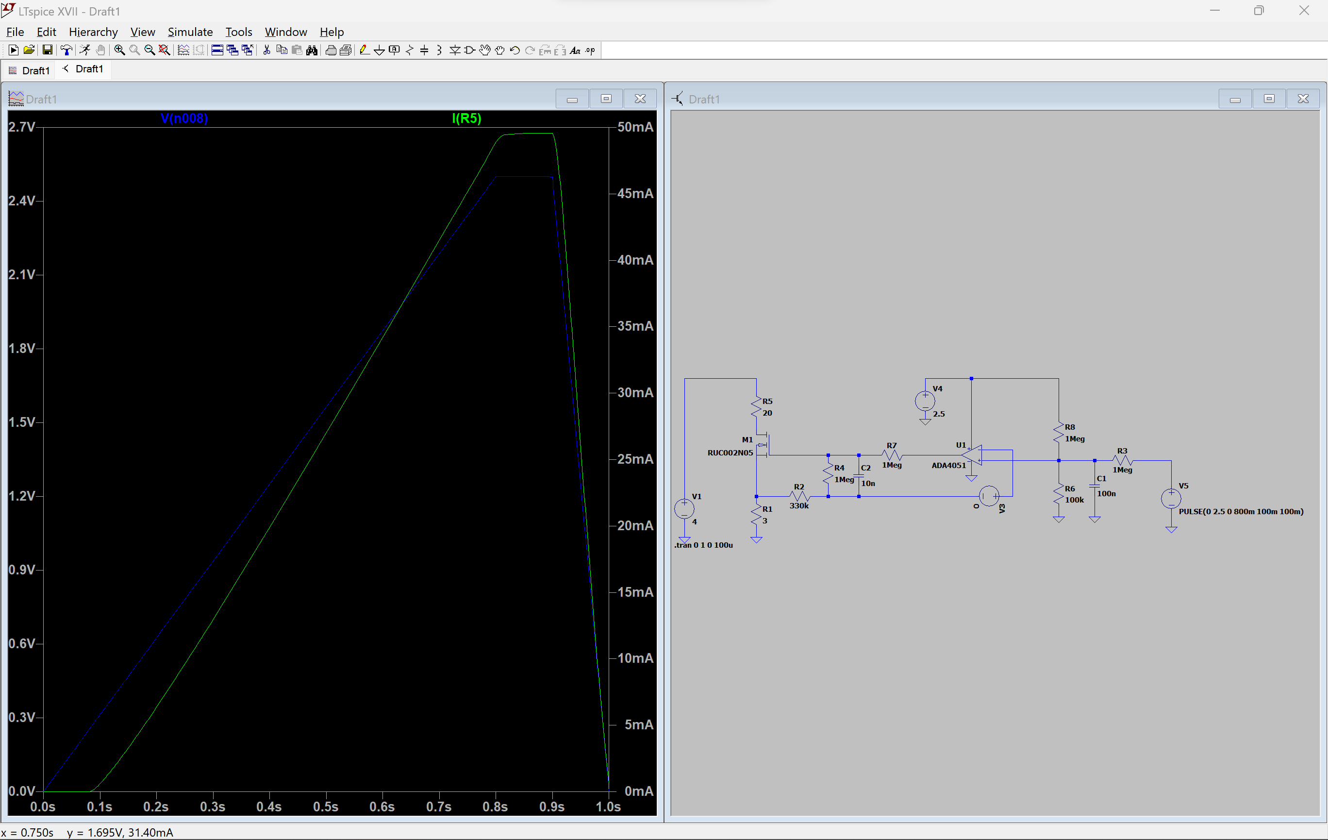
A concern I have about the linear regulator is that the offset voltage determines the minimum output current achievable that is guaranteed to be > 0. The MSP430’s opamp is specced to +/- 5mV Vos, which is not great. The burden voltage of the low side current sense resistor is ~200mV, so this corresponds to an accuracy of +/- 1.25 mA, which is pretty terrible. The way I get around this is by significantly reducing the open loop gain of the op amp to ~2. This will decrease gain accuracy due to variations in the threshold voltage on the low side fet, but what I get in return is a psuedo-exponential response input response. Meaning, variations in offset voltage and resistor tolerances will have a smaller effect at low currents, and also improves dynamic range practically acheivable.
The blue trace is the simulated PWM DAC input, green trace is LED current. Notice the small curve at the bottom of I(R5). Ignore the P/N of the op amp, I just chose one that seemed close enough to the MSP430 builtin. Depending on how well this works, I may have to switch to an NPN as opposed to a FET. The lower input impedance and tighter Vbe tolerance makes this exponential curve even more gradual. But I’m going to see how the FET works out this time since I can save a little PCB space by going with a dual-fet part.