Sorry, gotta ask. Edited: I’m not too lazy/ignorant to read though the whole thread, I just did, but it didn’t provide me with an answer…
The idea is to provide the MCU with a lower voltage on a multiple cell configuration? If so, why not just use two resistors and make a voltage divider?
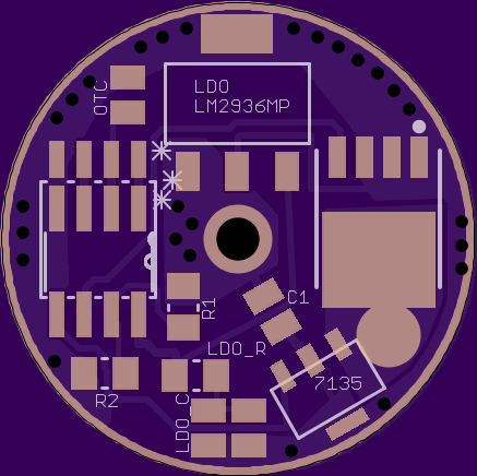
Damn, that board looks great! Love all the vias, positive lead through hole, MCU footprints and layout. Ordered a set. I'll test it and report back as soon as it arrives. Thank you very much. :)
Mike C,
Thanks for asking. The idea is to have as low of parasitic drain as possible to help prevent ruining cells. You have my attention. What size resistors would you use that would provide adequate current and voltage to power an MCU (in high mode) and a buck converter in a 4S setup? How much parasitic drain would it have?
I haven’t done any calculations on this myself so I don’t have any size recommendations. I guess it depends on how much current the MCU will use at the most. Parasitic drain will probably be higher than with the LM2936 but better than a zener. Should be able to get it down to about 1mA with the right resistors and firmware… but to be honest I’m just guessing really, I haven’t haven’t had to worry about this much as my double voltage drivers all have power switches so parasitic drain is not really a concern for me, I was just thinking out loud…
A side comment on something I picked up earlier in this thread… I’m using 1300K and 300K resistors for the voltage divider on my latest driver design which has OTC, momentary switch and voltage input on the same pin. I’m not having issues with the high impedance. I always do two ADC conversions, discarding the first and using the result from the second. So far the results have been very reliable.
Awesome news on your side comment. That's some cutting edge stuff you are working on there. Been wanting to catch up on it. I think you have some info on it in the Attiny 25 thread and maybe some other places. Do you have a dedicated thread where you are working on that? It sure sounds exciting given the space and pin limitations of our drivers.
No dedicated thread yet. I was going to make one with the latest driver but got a problem with voltage always on the FET pin so I’ve pushed through a new design with OSH Park that I should be getting within two weeks or so. I don’t know what caused the problem so I don’t know if I’ve fixed it, but should be ok with the new one as I’ve increased isolation for all signal paths and moved some stuff around a little.
In the meantime I’ve ported my ATtiny84 dual switch firmware to the 85 with this three for one pin design, and am using the above mentioned board (with FET removed) to test it all. I’m just about to put it in a light for testing (which I’ll probably end up giving away soon as I’m reaching 1000 posts fast…)
I have to say that I am very happy with the LM2936. My mods with it are doing great. I haven't been locking them out and they holding cell voltages great. I just wish this regulator came in a smaller package. The micro regulators I have looked at have much lower voltage input range. Since I have a lot of 4S lights, I like the cushion the 40V capacity gives.
I have received your boards from OSH Park pyro1son. I've been trying to figure out what light to put the first one it. I have decided on the Fenix TK75 with 4S2P cells, driving an XHP50 and 2 XM-L2's (all in series). I will be reflowing right after I log off.
I'm looking forward how you go with your led set up. With the light I built using a similar reflector (Shocker) with two XML and a single MTG-2 l ended up removing the MTG-2 and running three XML-2. The difference was not as great as I thought it would be. The XHP70 with its extra output may be the way to go.
Thanks for that info. I'm getting close to finishing that light. I'll report back on it.
pyro1son,
Your board works well. I'm not using a AMC7135 in this build, but it looks like it should would fine. I have taken a couple pics that I will posts soon. Thank you again for creating it. I have a little feed back, but nothing serious:
I'm a little concerned with how thin the exposed top ground "ring" is. Doesn't appear that it will make good contact. I don't need it in my current build. I will augment it on future builds if needed.
The AMC7135 pads are a bit close to the edge of the board.
Not sure if this is an issue. I have noticed some of the traces are quite thin. The ones I noticed are low current traces. So they are not a problem. I need to check the traces that handle more current to make sure they are thick enough.
Ummmm. Hi. I’ve built up a little test circuit with 10uF cap between positive in pin (pin3) and ground pin of a 5v LDO and a 22uF cap in series with a 4.7 ohm resistor in between the output pin ( pin1) and ground pin. I’m testing with 8 V at positive in (pin 3) with -ve of the battery connected to the LDO’s ground pin. I’m checking voltage with DMM+ at the output pin (pin1) and DMM -ve at the LDO’s ground pin and getting nothing… Did I connect wrong or would the LDO ONLY work in a nanjg for example where the output is pulsed (PWM)
I think you have the in and out pins mixed. The VIN pin is the right pin (one connected to a cap and then a resistor) in your picture. VOUT, the pin on the left.
I need to update this thread. 4.7 ohms will generally be much higher than needed. 3/4 (.75) ohms is probably the best way to go on the resistor. I don't know if it matters, but I put the resistor first on the VOUT then the Cap between the resistor and GND.
Like the way you attached those to the legs. Looks much better than my similar attempts.
Yeah, that looks like it. Through me off too even though it is correct. I still get confused almost every time I hook one up. Bottom view, geez, why couldn't they just have shown a front view or something less confusing?