Sorry Steve, I was re-reading this post…. enjoying your great work AGAIN…. and noticed the question. That day I was working on a 26650 light sized for an optic. It was a “Shorty”. Just over 5” long when finished. It was really a prototype, we will put these in production mid November.
Thanks for the comments guys. It helps a lot.
I’ve had the same thought as Justin on more than one member here, jump on a plane and go visit them that is, but unfortunately a couple of things on Justins list of why he cant is also on mine.
Yes RBD there will be two lights built hence the time taken to do the build. My problem with making two items at once means that if I stuff up one piece I have actually made the same mistake twice and yes I stuff up lots.
I’m not totally happy with the tale caps and think I will remake them in aluminium. The brass just isn’t doing it for me.
Your lights are amazing TL. Dont forget to post some pictures up for us. :+1:
Sneaky b, if the world stopped turning would momentum pile us all up against the Himalayas? Then we could all visit in one place and annoy everyone with our lights.
With the change in plan from this light using nine cells to six I’d decided that the large diameter battery tube would be the long one to hold onto. When I got up to this stage I had a change of mind and the smaller diameter battery tube will now be the longer of the two. With this plan in mind the build continues.
The driver had arrived from RMM so a couple of driver retainers were machined up along with six 8mm diameter and 5.5mm long brass pedestals.
The brass extension pieces are to extend the positive ring of the driver above the driver retainer. The driver retainer also had a spigot machined onto it to locate the battery tube centrally.
The brass extensions were then soldered to the drivers. These were later resoldered with a little more solder paste applied. I did purchase a hot air gun to specifically to do this step and it worked like a charm. Well I hope it did. I haven’t tested the drivers yet. :person_facepalming:
O’ring grooves were machined into the base of the battery tube and at the tailcap end to keep small rodents out. The o’rings used are standard C8 bezel o’rings. As the plan had changed on the battery tubes the three bolt holes were drilled all the way through as the two battery tubes will be held together with three 100mm x 5 mm stainless cap screws.
The larger diameter battery tube was then parted to a depth that was not far enough to part off. A small step was machined into both ends of this part to centralise the battery tubes together and to the head.
In the Old_Lumens tradition hand tools were used in the making of this light.
A shot of the assembled light. I’d guess I’m just over a third of the way through this build.
I’m undecided yet, meaning I dont have a clue on how to do the switch and whether to put a handle on to hold the light. Any suggestions greatly appreciated.
Thanks again for following.
I’m thinking forget the oven mit and go with wheels. Maybe a bi pod with a control stock out the back. Then you just push the light along out in front of you as you hunt for battleships/tanks/missile launchers, that’s what the light is for, right? I want to see that part that bolts on to the helicopter/UAV.
Its five months since this build was started and progress at a steady rate continues. I keep thinking to myself that there is more work in these battery tubes than in the last few lights I’ve built.
As the light was originally going to use nine batteries but now only six there is a short extension that the longer battery tube will bolt to with three 100mm long x 5mm cap stainless steel cap screws and this short extension will bolt to the head with six 3mm x 25mm long cap screws. The screws thread into the head 15mm so there should not be any issue with the head falling off with the small diameter cap screws.
Here is the short extension before the six holes are drilled and after the holes are drilled.
The holes are countersunk 5.5mm, the diameter of the head of the cap screw.
Next is the head with the holes drilled ready to be tapped. Just tapping these twelve holes (two heads) took a couple of hours, all the time fearing that the tap would snap.
And here is an end view of the assembly showing the three 5mm and six 3mm cap screws.
The tailcap was profiled at this stage. I’m not sure yet but l will probably do a little more to it after the rest of the light is finished.
The long battery tube was set up in the mill for profiling. Machining this one tube took almost the whole day. the second one is still to be machined. This is the first cut of many.
The second stage was to machine a flat between the radius cuts.
Lots of machining later we ended up with this.
A couple of views of the machined battery tube next to the yet to be machined battery tube.
And finally the two battery tubes bolted to the head.
I’m still not sure what to do about a switch but hopefully a light bulb moment will happen any time soon.
Again thanks for the comments guys.
As we say in the south, “That’s plum perty!” :+1:
If you do go for a handle it going to need to be just as well-designed- perhaps you could locate the switch in it?
Trigger. That would be different. Can you please send me a diagram of your thoughts Suncoaster.
If I put a handle on it It would probably have to clamp on as there is not a lot of spare material in the battery tubes.
There is plenty of room in the driver cavity for a switch as I built it large enough for a driver swap in the future if it was ever needed.
Thanks Dan. The V Blocks have come in reel handy. They are one of those items you wonder how you got along without them.
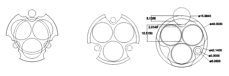
The shape of the long battery tube is pretty much what I drew up in the diagram in the op when I was playing around. Here it is here.
The handle could attach to the head, and a ‘trigger’ co-opted from a power tool might work- plenty of those out there to choose from and some can carry quite a few amps
For me it would depend on balance, if the light balances well in the hand then I’d put the switch on the back of the head but if it’s head heavy then I’d add a handle and mount the switch either on top as a thumb switch or underneath trigger style.
When the second battery tube is machined I’ll start on the head to get a better idea how well its balanced. I cant see it being head heavy with six batteries in the tube, copper earth thingy and brass tailcap. Its going to look a little odd as the head will be as long as the battery tube. I think I’ll stick the switch in the driver pocket area for the time being but then who knows.
Work restarted on the head with the switch first up. A sketch was drawn up to make sure it would all fit.
Happy that it would all work the head was clamped onto the bed and machining of the switch area commence!
The area for the switch machined up ok and six holes were drilled to tap to 2mm. Unfortunately my abilities to snap of 2mm taps continues so this is still a work in progress to work out what to do. Only one head has had the switch pocket machined at this point in time.
A step was machined to allow access to the area allowing drills and taps to reach the bottom of the switch pocket.
The heads were profiled which may change yet depending on how they look with the battery tube attached.
The cooling fins were then machined. The thin fins are 2mm in width with a 3mm air gap in between. The depth of the fins follows the profile of the inside of the reflector housing with about 5mm wall thickness.
Small taps seem to be made more brittle intentionally just to frustrate us Not being “smart enough” to have the proper stuff, I began my career in metal tapping by using whatever I had, selected by eye. In that process I learned that a slightly oversize drill can still leave you plenty of thread to hold save for high stress or high fastener torque applications and it makes tapping much easier
So looking at a drill chart I see M2**.4 calls for a 1.6mm (0.063”) drill. The next size up is a #52 which is 1.6129mm (0.635”). Just a tiny bit bigger so it should work. M2**.25 calls for a 1.75mm (0.0689”) drill and the next size up is a #50 which is 1.778mm (0.07”) which should also work. Of course you’d test it on some scrap first which I’d have done before posting but that stuff is in storage elsewhere so I can’t.
Yes it’s unconventional but in my world either something works fine or it doesn’t, and if it works fine there can’t be much wrong with it :sunglasses: