That’s amazing, how does one get started on building a driver?
That’s good to know. Are there any disadvantages to a driver with more modes? I’m thinking of choosing one with memory, 5 modes (Moonlight to Turbo). As to the other options i see on the mtn website, i’m completely overwhelmed! No idea what to choose.
If i haven’t got it misunderstood, this driver can work with up to 3 batteries. So it can work with all 3,6 and 12V LEDs i assume?
By the way, how does a contact board + repalcement driver setup look like? Would you mind posting a picture of such a setup, because i can’t imagine what one looks like, or how i can fit that into the J20 at the moment? Thanks.
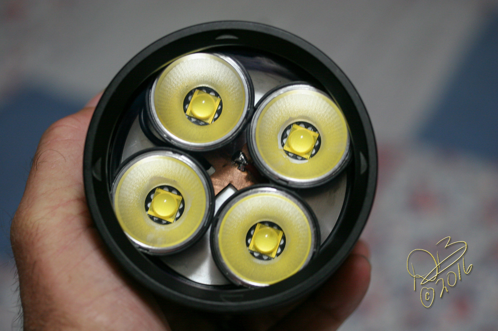
I simply stripped the existing driver and piggybacked in an FET with Zener mod, put 4 of the 9V variant MT-G2 on individual 20mm Noctigons then a Ledil reflector in it’s holder on top of each of those. I’m getting right at 15,000 lumens on 3 of the big Trustfire 32650’s.
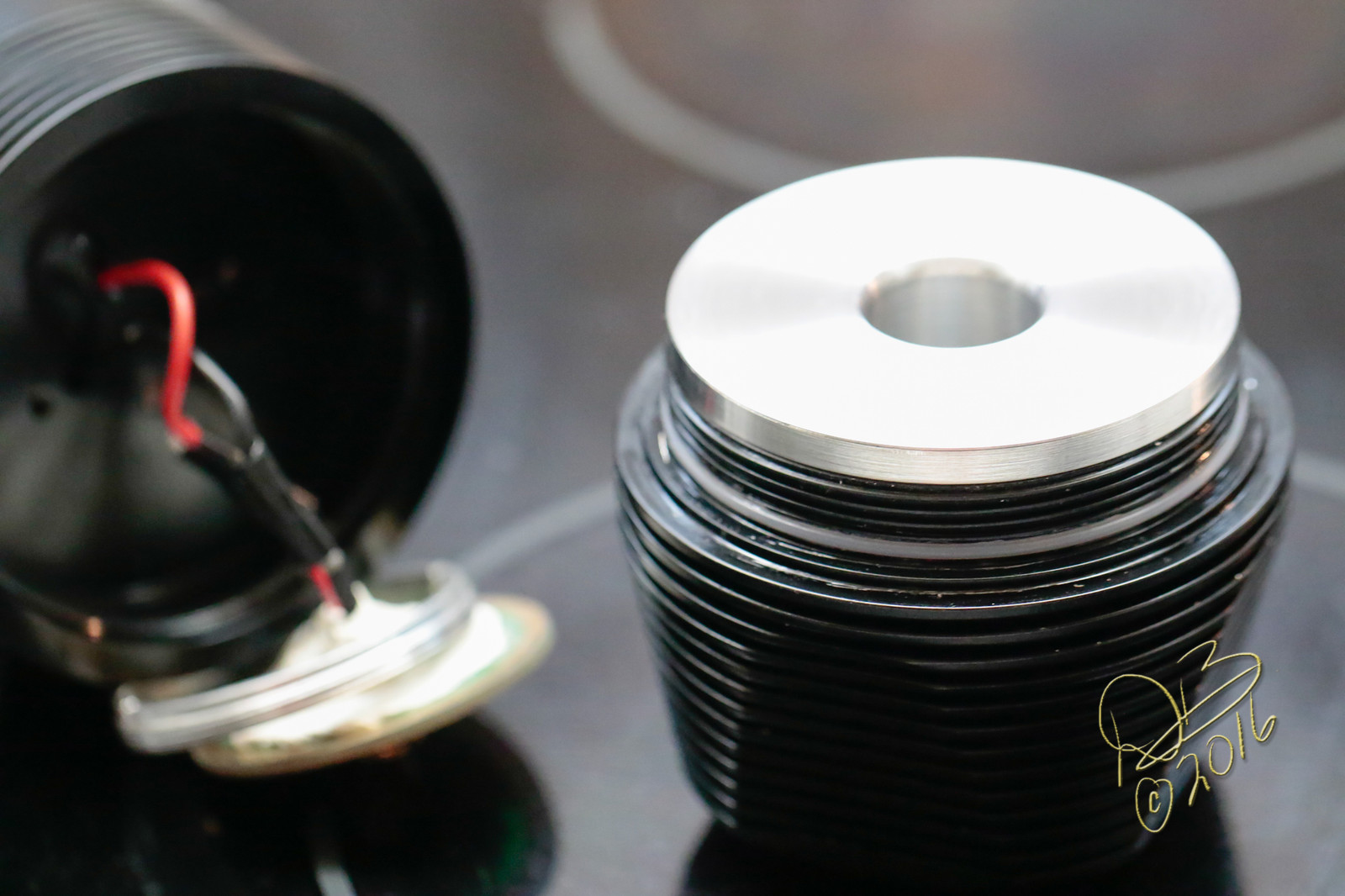
To handle the heat, I put a 1/4” thick aluminum spacer on the emitter shelf and made a massive head filling heat sink to spread the heat more efficiently to the finned area.
Original switch is handling it fine.
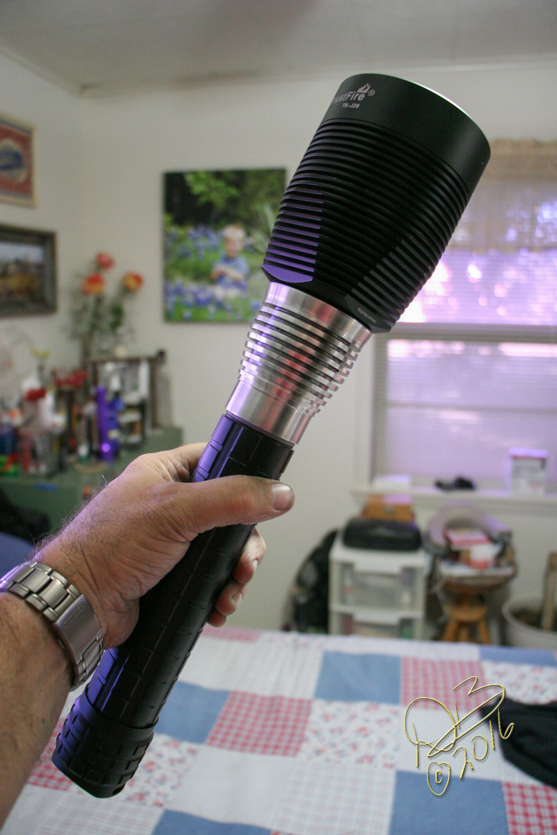
So yeah, 3S cells to 4P 9V MT-G2 emitters. Definitely not a throwy light, but a very nice tint and just a huge amount of output.
Edit: With the cells rested and not fully charged I’m seeing 20.85A on the 3S cells at the tail end.
Five modes is nice. No particular advantage to any of them, really just personal preference. I like to keep them simple and don’t really go for all the hidden mode stuff, but lots of people seem to like that too.
These FET drivers will work with pretty much any amount of batteries and any emitters so long as you match the correct current to the right emitters.
I don’t have any pics but it’s fairly simple. The existing driver just ends up with two wires hanging from it with the new driver hanging just below it. You can “pot” the new driver. Which just means you encase it in something like a thermal epoxy and stick it to the old driver. This helps to keep the new driver running cooler. But you don’t have to do that part really.
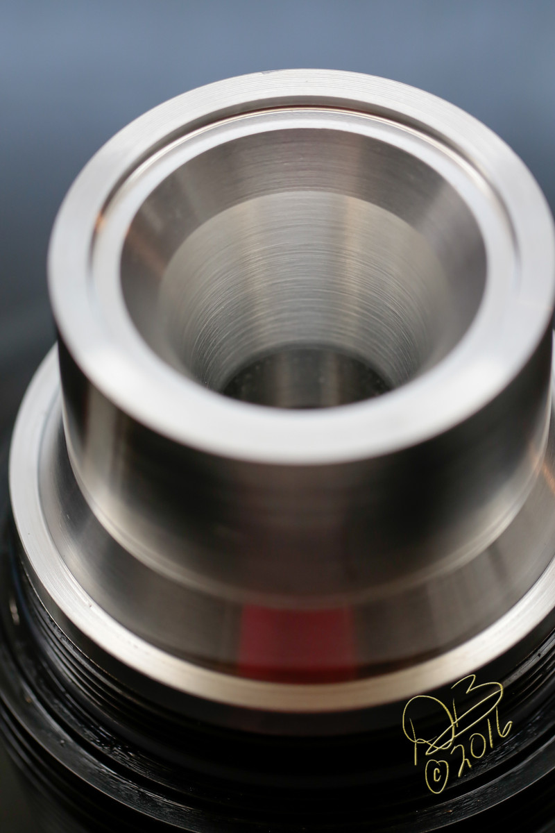
The finned head section is hollow, a retaining ring holds the driver in from inside the head instead of below… there are 4 screws originally through the emitter shelf into the reflector, so I machined the inside heat sink to have a hole to fit around the holes and allow passage of the wires through to the emitters, the base doesn’t screw all the way into the head by about a 1/4” so the heat sink sits on top of the base such that when the parts are screwed back together the heat sink is pressed up against the bottom of the emitter shelf. I flared the hole in the sink out as it drops down to the driver so it clears everything easily and directs heat outward.
The first picture shows the additional 1/4” thick aluminum plate under the emitters. I used a sheet of copper to join all the positives on the mcpcbs with an 18ga lead soldered into the sheet. 18ga leads leapfrog around the perimeter to join all the negatives.
The light is rather large, so this heat sink is bigger than the pictures make it appear.
That sounds insanely awesome! Must look one hell of a lightsaber haha. Just one thing though, is it then impossible to do 6V XHP’s with the piggybacked driver in the J20? If so, is that because it is direct drive without a voltage step up/down function? Sorry if this is a stupid question by the way.
Would copper do just as fine? I mean it does conduct heat much quicker, although it also dissipates much slower than aluminum, from what i’ve read. If i were to run the light at turbo for a few minutes would the material make a difference?
Damn, that makes me want to learn something about CNC machining! The things i’d do with it… maybe go overkill and do a 10” LED spotlight! But i guess by then there wouldn’t be much sense having the relatively minute XHP35HI, but rather an HID setup…
…. you know if you hadn’t told me that i’d have done it the exact opposite way!
Is there a good thermal epoxy at a reasonable price? I reckon i’ll need that if i’m going to go all out on this. And the fact that i haven’t got any CNC lathes to mill some custom heatsinks or whatnot
You can see the white epoxy potting my little 17mm FET driver to the big contact board, on the left in the second and third pictures. I figured with this big heavy light it’s inevitable that it falls or gets dropped so I potted it for durability.
Since I am using 3 cells I wanted to match the emitter voltage. Pushing the 9V MT-G2 pretty hard it has about a 11.3V forward voltage so it takes the 3 cell configuration nicely. I’m doing the same in a BTU Shocker as well, with 3 of the same emitter and using 18650’s in the beefed up carrier.
You could run 4 6V emitters, 2S2P and they should do fine. There’s all sorts of ways to configure a light this size of course. Richard replaced the XM-L’s with XHP-50’s and I made him an extension tube for a 4th cell along with the big heat sink. He got 39,000 lumens and it would run with the sink to kill cells. Initially, without the sink, it was too hot in about 30 seconds. So yeah, there’s all sorts of things you can do with this huge beefy light.
Copper works better but is so much heavier. In a light this size, already quite heavy, copper would make it a brute! And I do love me some copper, so I’m not saying that out of hand. I build a triple XHP-50.2 from scratch and the copper pill was 3.17 pounds when I started out.
Was looking for 15,000 lumens out of this one, it “only” does 11,833.
Definitely Some works of art being made out of the TR-J20! I’ve made it into my new project light. Started upgrading the mosfets but I botched my first board by lifting a pad. Got a replacement driver from Trustfire and it looks like the new ones have 6 mosfets instead of 5. With one of them being stacked. Replaced all 6 of the Mosfets with IRLR8726TRLPBF from MTN electronics. Did the resistor mod and it already seems brighter than before.
Trying to get as much power as I can get out of the stock driver and running 12 XHP50.2 I’m looking for some good output while still keeping it efficient.
I think the TR-J20 was the pinnacle of the multi emitter budget lights. Nothing since has matched the quality, heat sinking, output that modders loved. With a price that said “rip me up and rebuild me.” It’s real limit was 3 batteries, even 32650’s couldn’t put 12 emitters into the overkill zone.
Is there a right way to potting the driver? I mean, could one ruin anything when potting?
If i ran 4 emitters 2S2P with 3 batteries, wouldn’t they have a forward voltage that when combined per string exceeds what the batteries can put out, say at 5A per emitter? What would happen in that case, would more amps simply be drawn out of the batteries, and even more as the batteries are exhausted?
39,000 lumens! How come i haven’t seen any photos of that on BLF yet haha how many amps does Richard’s draw at that output? I imagine his would have been modded with an e-switch?
The extra weight’s not so bad, not when you come to think of it as a light cannon, it all just makes perfect sense! I know i’d love something like that
It seems to have more potential. I never tested it with the stock mosfets on the replacement though. Need to do some tailcap and temperature tests. I’m thinking that with the low resistance of the 12 xhp50.2 it should output some more amps as well…
Thought about double stacking all the mosfets as well, we will see how ambitious I get
I see the potential. The head and reflectors are good to go with very little work. I thought that the heads would make good off road lights years before the XHP LED’s.