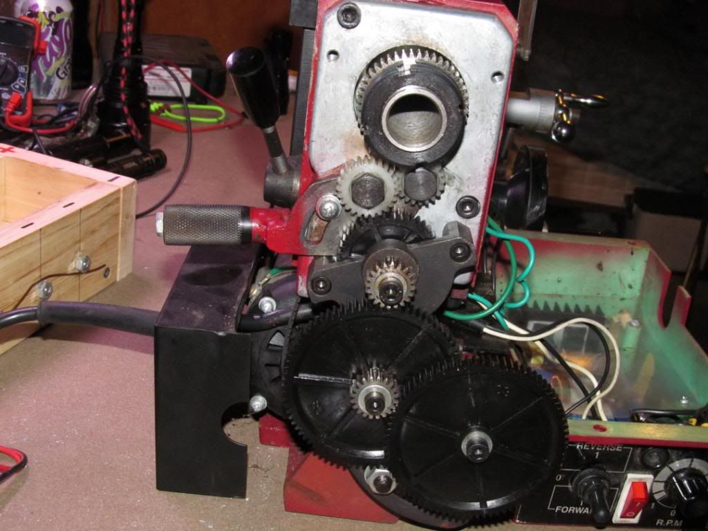
Maybe someone here can help with this. I came across this lathe yesterday. It doesnt work right now and it is missing two of the jaws in the chuck. I will worry about those after I get it running, if I can get it running.
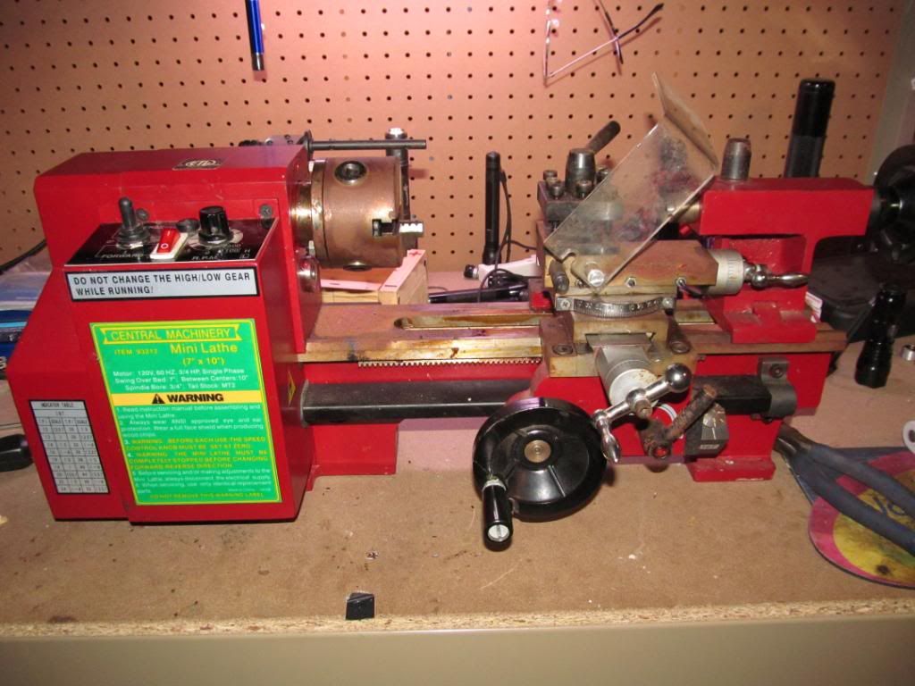
When I plug it in and hit the power switch it doesnt do anything. The power switch lights up but thats all, not even any sounds. There is a small fuse on the top of the power panel, I checked that and it is good.
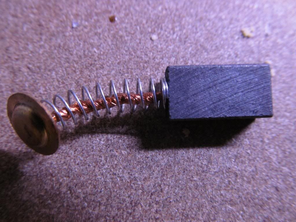
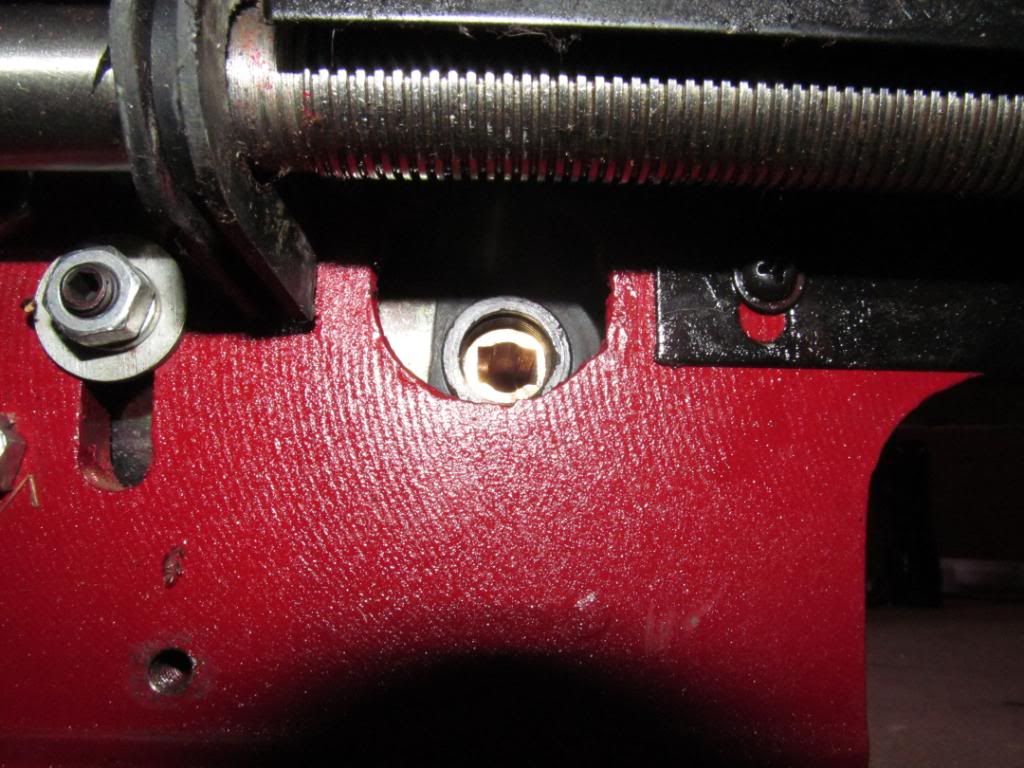
Below the bed there are two small plastic caps, one on front and one back, that look like fuse covers. These covers hold these things in and opposite each other.
They go in these holes.
I don’t know what these are for. The ends of the small blocks with the springs on them are very slightly concave, like they press on either side of a shaft inside. I wouldnt think too much of them except that the copper wire inside the spring really makes me wonder what the function of these things is. Maybe some kind of static control, I have no idea.
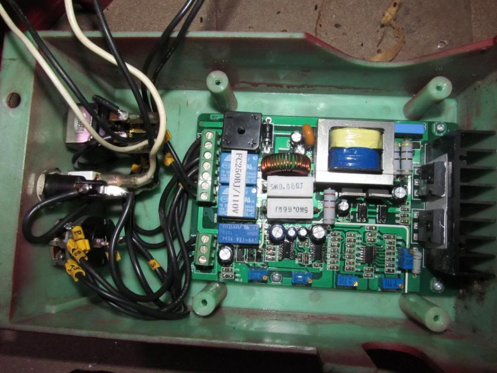
Here are some other pics of the unit. If anyone has any experience, insight or off topic joke that they think would help, send it. Maybe the problem is something simple.
Forgot to add, this is a true budget deal, it was free. Any help is good help.
Your mystery items are brushes from/for the motor. It looks unusual (to me), as it appears to be a DC motor. The circuitry must be some sort of rectifier and regulator assembly.
I’m going to study your pictures for a while to try to make some sense of them.
Can you turn the motor by hand ?
Can you turn the spindle by hand ?
You can probably find the answer on a dedicated “mini lathe” forum like this one: http://groups.yahoo.com/group/7x12minilathe/
The same company makes them for different retailers.
So there are a lot of common parts, and problems, between brands.
If you are lucky, one of the switches is faulty.
The chuck should have 2 sets of jaws, internal and external.
3 pieces in each set, 6 pieces total.
Hopefully they are available separately.
Those graphite things are definitely brushes for a dc motor, so there must be some kind of transformer/rectifier set up to convert the ac mains input to dc voltage.
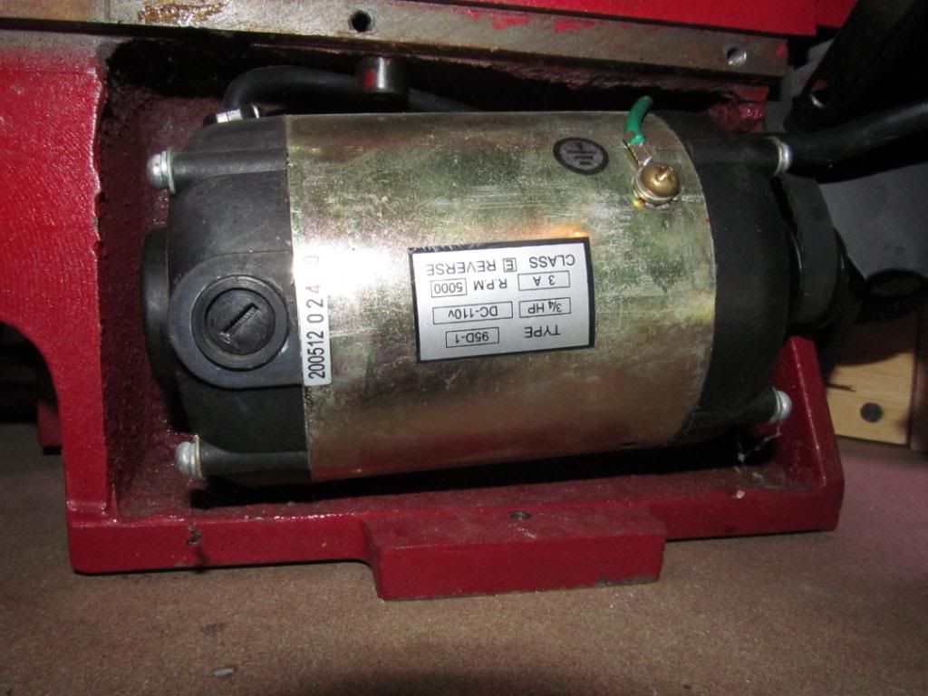
I’m pretty confident you have a digital multimeter so I would start by looking for a bridge rectifier/ 4 diode array and testing the diodes. The motor should have a plate somewhere that descrides what voltage it requires, then you can test what if anything your getting.
Those brushes look to be in good knick, so the motor has probably done little, which would suggest the transformer/rectifier has done little too I suppose. Can’t understand why you would build a lathe like that though, its not like you’d keep it in a vehicle to run dual voltage so its a bit confusing.
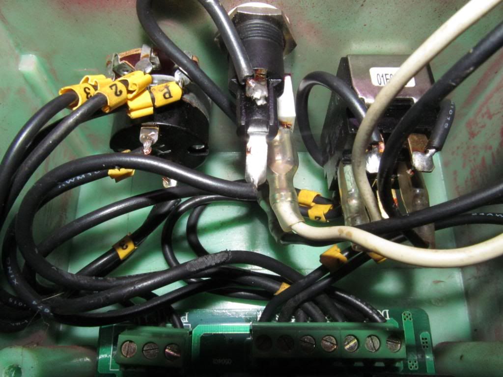
Edit, you found the plate and I didn’t look at the pictures, the motor says 110v dc. Are you getting anything across the motor leads? Next thing is to trace them back to the relay and from there to both the on/off switch and transformer/rectifier as the main plate says * 60hz which is ac (not trying to teach you to suck eggs here sorry).
Check to make sure the main switch is letting the 110V in and out.
A cheap bad switch will make you crazy
A non-contact voltage tracer will speed things up when tracing circuits.
This is what I use everyday for work.
I just had a breakthrough. I was looking at this site http://www.dcmotorcontroller.net/. This is not the exact board I need so I searched for the board that this machine uses and found this
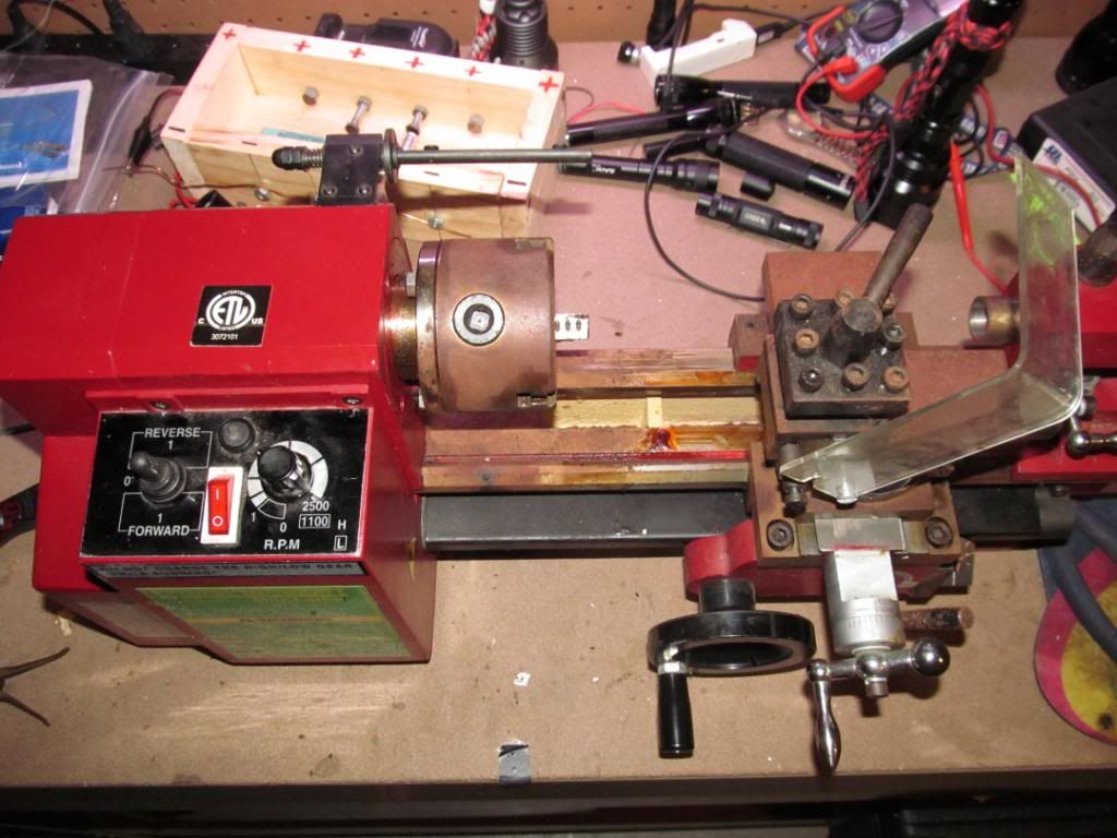
Motor Controller, Harbor Freight Mini Lathe 3149 - LittleMachineShop.com. Note the safety switch on the chuck guard. Mine does not have a chuck guard but it used to, I see now. The bar and switch are still there. I powered the lathe and turned the bar until I heard/felt the switch engage. Turned up the speed dial and the motor turns like a champ.
The belt from the motor output to the gears is super loose. I have not really looked at this next problem too closely yet, I was so excited about getting the motor to turn that I had to update here. It seems from a quick glance that the belt is so loose that I think there must be some kind of tensioner in there. I just don’t see how a belt could stretch that far.
We have a winner!!!
And for free ![]()
Looks like you just have a lot of cleaning and adjusting to have a nice little machine.
Congrats on the find.
That's awesome!
Next thing you know, Lang will be turning out $700 HaikuCJL custom lights. Just remember your friends from the old days. We loved you before you were famous.
Foy
SCORE !!!
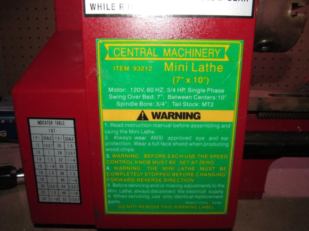
That lathe is sold by Harbor Freight you can download the manual here. Scroll down to Product Manual and click on it.
Lookin’ better all the time.
Grizzly sells basically the same thing, http://www.grizzly.com/products/7-x-12-Mini-Metal-Lathe/G8688
Some of the details may be different.
Note the link to their manual, parts list, etc.
I only see one set of jaws listed, #166.
The other set comes with the chuck, #2,
might not be available separately.
HF shows both sets of jaws, #166 and #168, on page 15.
http://manuals.harborfreight.com/manuals/93000-93999/93212.pdf
The mystery items as mentioned earlier are definitely motor brushes. (soft carbon, to run against the commutator of the armature to reverse the polarity to the armature windings and the magnetic field to keep it rotating).
The motor is most likely a shunt wound field dc motor. They are often used in Lathes as they are good at keeping a constant speed under changes in load.
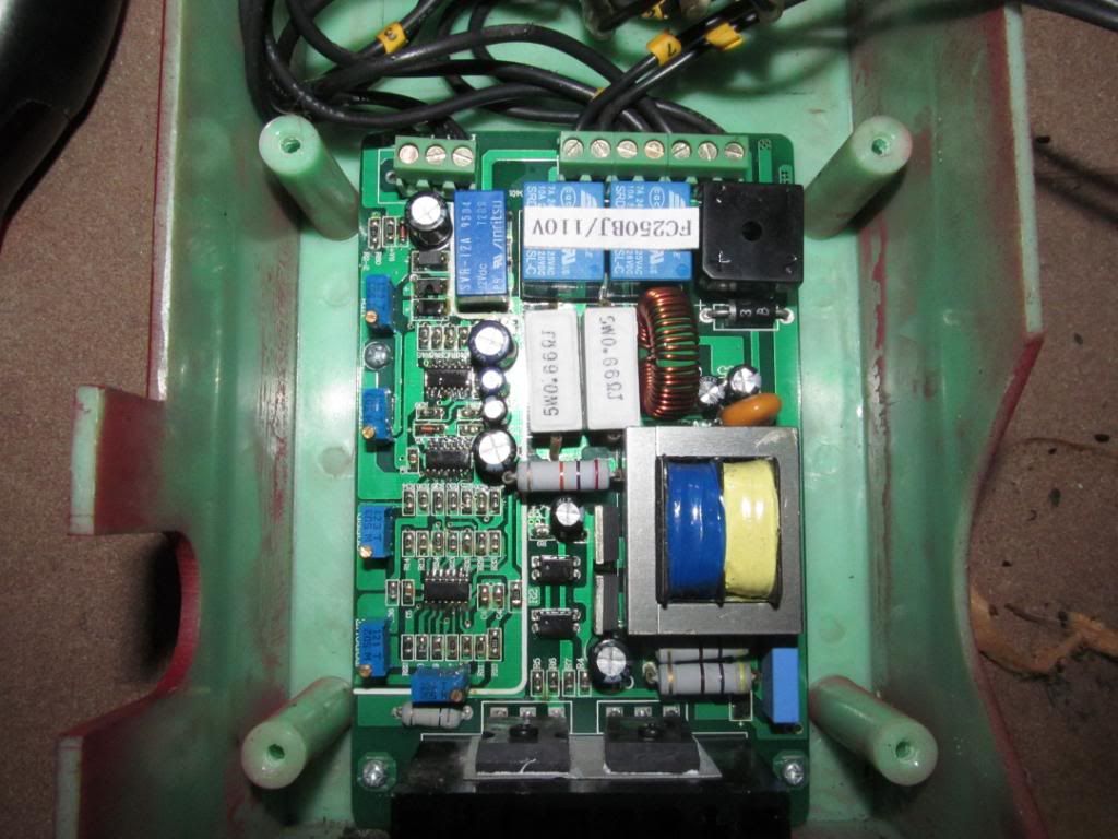
In the picture below:
The black square in the top left with the +,- and two ~’s is the rectifier, the transformer is the yellow and blue device with the steel surround in the middle near the top. You can see the Mosfets (maybe SCR’s) on the far right attached to the heatsink. One of the smaller IC’s at the bottom will be a PWM chip that will be controlling the ’fets and your motor speed.
I am jealous of your find, with a bit of work you should be able to make some very cool items!
Congrats!
Ford
Thanks for all the help guys. The story behind this is that one night I showed a guy I know a mini mag that I had modded with an XML using Matches guide. The guy was really impressed and wanted me to show him how I did it. As I explained it to him I showed him the caveman approach I used for boring out the head with a dremel. it doesn’t look too bad and it works but it’s not the best way to do it. My friend then tells me that when he bought his house the previous owner left a lathe there. It didn’t run and he just never got around to throwing it out because it was so heavy. He said it was mine if I wanted to tote it out.
So ultimately I have Match to thank for this.
I think you need some duct tape to really get it working right. 
If you don’t have one, you’ll also need a chuck key.
A revolving center, and drill chuck, would be nice.