Just completed this gem after many modding hours.
- Triple XPG-2, 5000K
- Max Current = 4.2A on a single 26650 battery (1.4A per emitter)
- Modes = H, M, L
- Weight = 170g without battery
- Switch = side clicky


----------------------------------------------------------------------------------------------
Update 3/29/14
The host for this build was a budget 2C light I bought several years ago that had a weak boost circuit driving a generic LED. I modded it once by replacing the LED with an XPG and wired two generic boost drivers together in series. However, it never really grew on me and has sat idle waiting for something better....
Ever since I saw the compact triple XPG DQG 26650, I wanted to build something very similar. I looked at my 2C host and came up with the idea to create my own version of the DQG.
The stock host was very beefy, but needed to be cut down to a manageable size.
Stock

Cutting tailcap
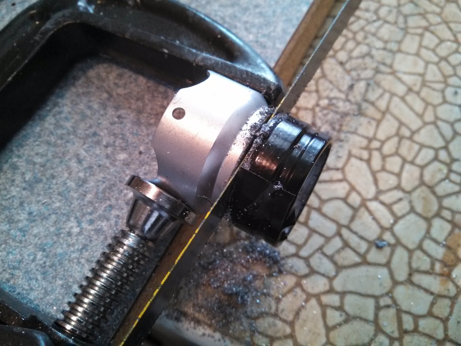
After
.

The stock components from left to right
(1) Remainder of the head which will serve as the bezel
(2) Driver pill which screws into the top body section
(3) Top body section
(4) Battery tube
(5) Remainder of tailcap


The body needed boring to fit a 26650 battery and Maglite C switch. I used a sanding drum attached to a cordless drill. The body heated up quickly while boring so I used gloves to insulate my hands and chilled down the tube on ice during the process to keep it cool
.


Now the 26650 slides right in with no resistance.
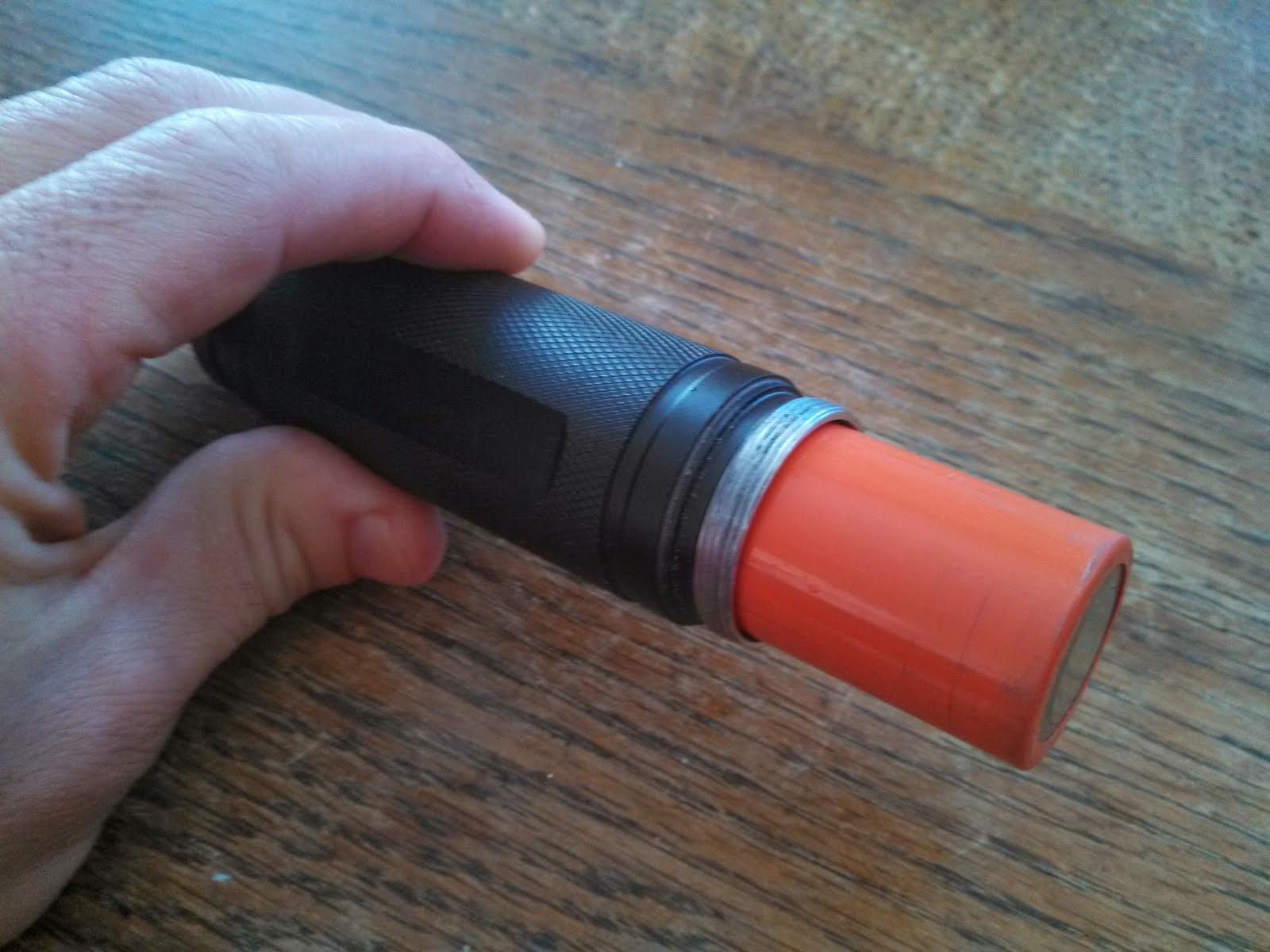

And the same for the MagC switch.

Rough assembly of body, tailcap, battery and switch.
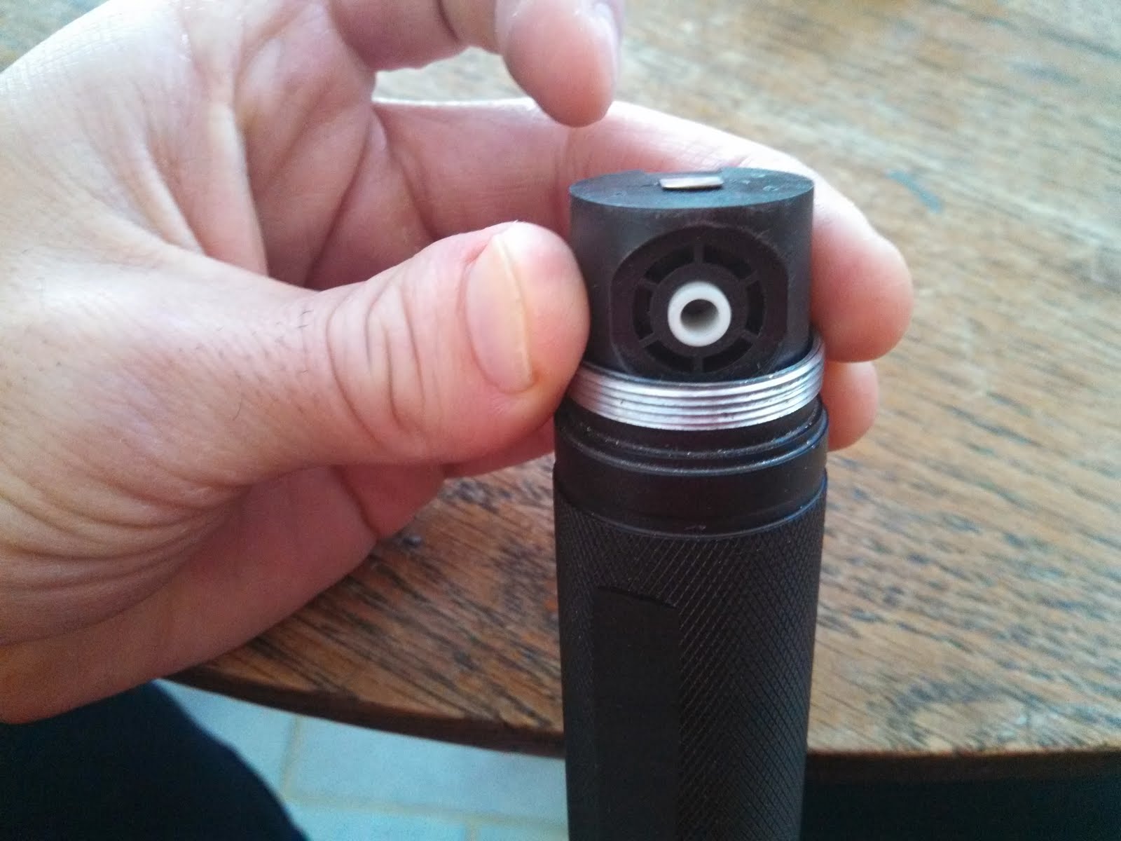
Top view

Bottom view. There is still an issue with a hole in the tail cap that remained after cutting. More on how I solved this later...
Now that the body was roughly done, the next step was to figure out assembly of the optic, LED, and driver. The stock light already had a nice screw-in pill design, but it was hollow with no surface to mount the triple XPG-2 emitter or driver. Fortunately, I discovered the triple optic fit perfectly, so it would be used as the optic holder, which would then screw down ontop of the PCB to hold it snugly in place.
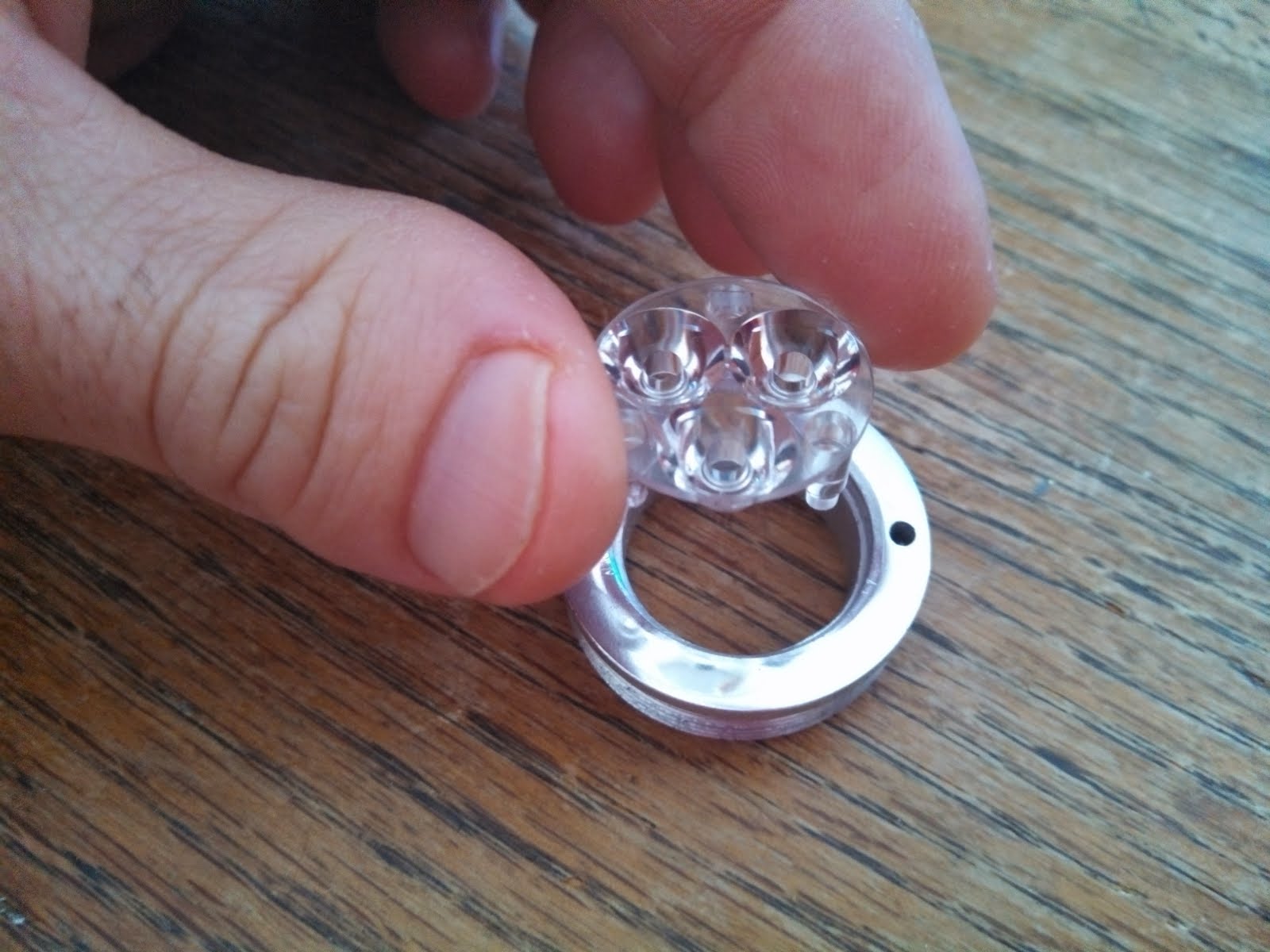

For proper emitter board fitment, I needed to dremel a groove on the bottom side so it would sit flush.


The LED/driver pill was made from several different components. From my spare parts bin, I found several pieces that would fit together nicely.
From left to right:
(1) Pill from another light.
(2) Ring
(3) Another pill from a different light.

For the driver, I cut the smaller pill in half. The bottom side was designed for a 17mm board, so this would be used to hold the driver.


After cleaning up the rough edges, the driver side fit snugly into the bottom of the larger pill


Lastly, the ring would be used to hold it in place. Again, as luck would have it, the threads of the ring were a match to the host, so I simply screwed it down, allowing the new 2 piece pill to drop right in. Here I’m showing a mockup of how the pieces assemble together.
Installing driver retaining ring.
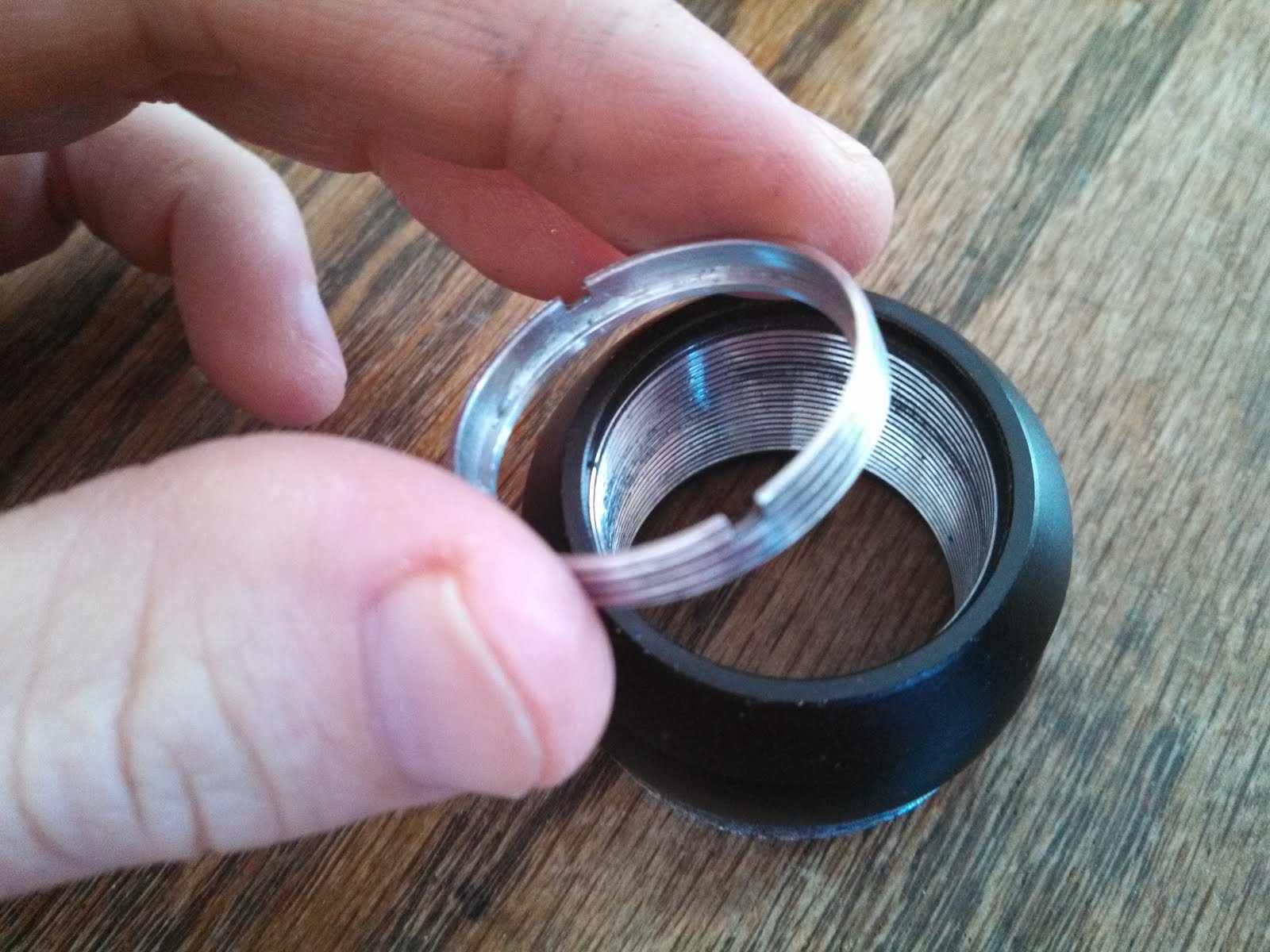

Ring installed with body and switch assembled.

Pill now “drops” right into place.


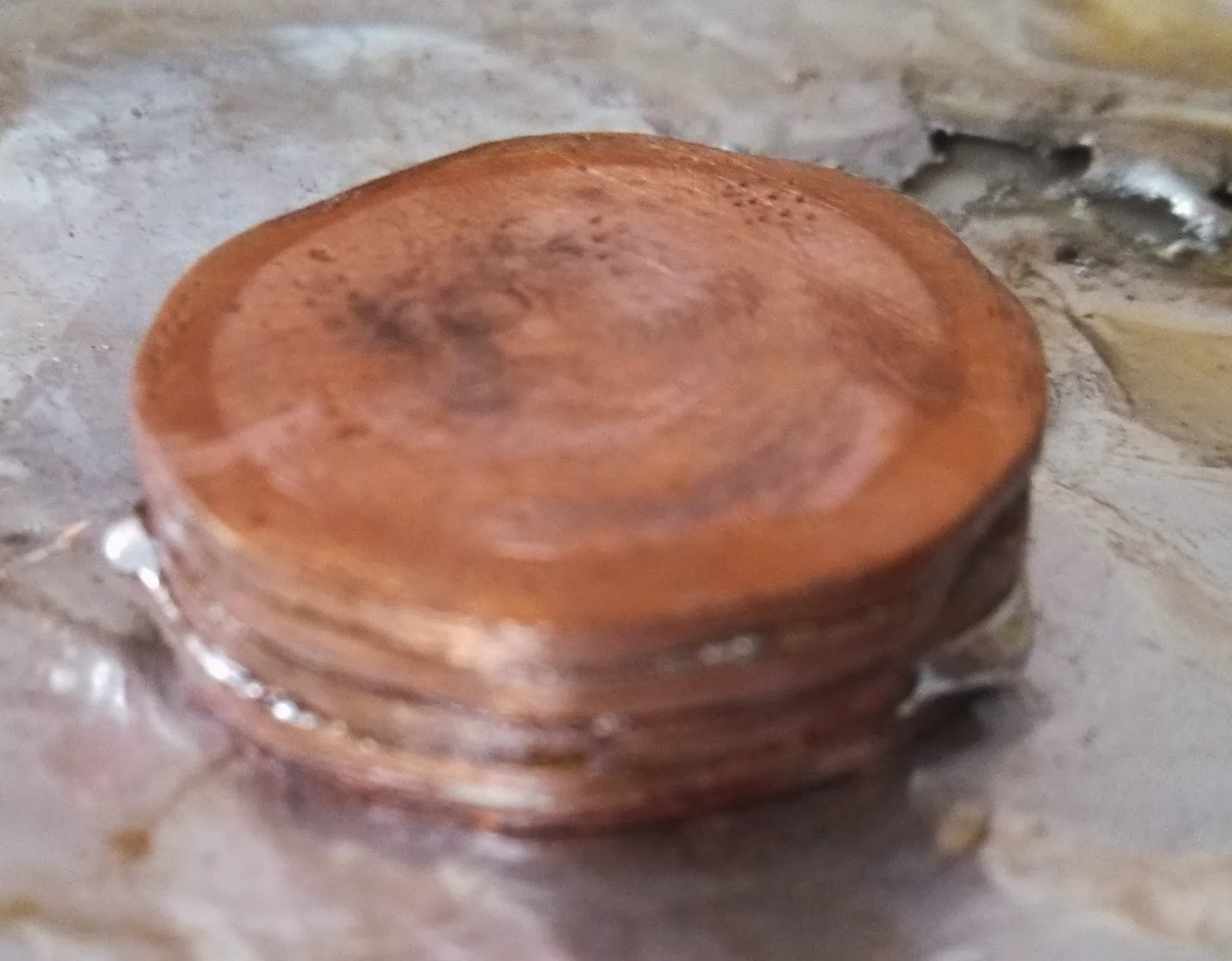
Now, I still needed to create a flush surface to mount the LED, so I took a lesson from O-L to create a copper heat sink. I used a ¾ inch copper couple which was split, flattened, and cut into circles. After tinning, they copper discs were secured into a C-clamp and heated with a torch. As the solder melted, the clamp was tightened to squeeze out excess solder.


Heatsink after soldering and cleaning up

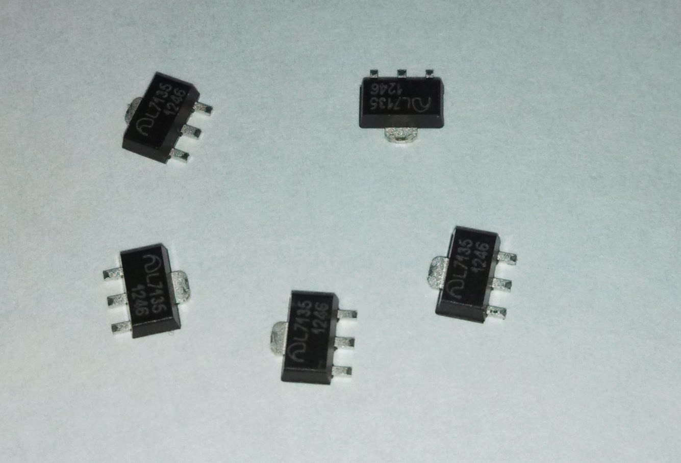
Now it was time to work on the driver. A triple XPG-2 wired in series could be driven up to 4.5 amps (1.5A per emitter), so I needed to add extra AMC 7135 chips to a stock 2.8A driver. I calculated 5 additional chips should be right on the money (13 x 350mA = 4.55A). My experience soldering extra chips to a driver has been hit or miss, so I wanted to minimize excessive heating of the board and try a different approach. I decided to wire all 5 chips together at once, then solder them to the board lying horizontal.
Chips were held in place with a clip while soldering.
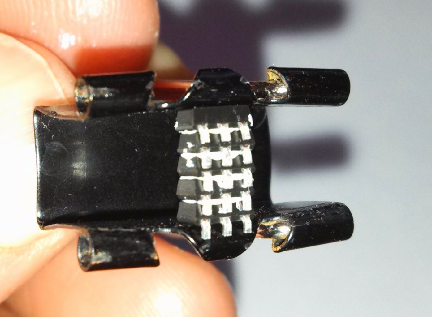
Wiring to the board and emitter to test output gave 4.49 amps which was very close to the predicted 4.55 amps.


I had to shorten up the wires so the 5 stack could lay horizontally on the top end of the board and still fit into the driver space in the pill. Soldering was tricky as it was hard to see, but I did manage to get it done. Here are a couple of close up shots of the driver in place with the 5 stack laying horizontal.


The next step was to complete assembly of the heat sink and wire up the emitters. First, the driver pill needed to be pressed fit into the emitter pill, and wires fed through the center hole.
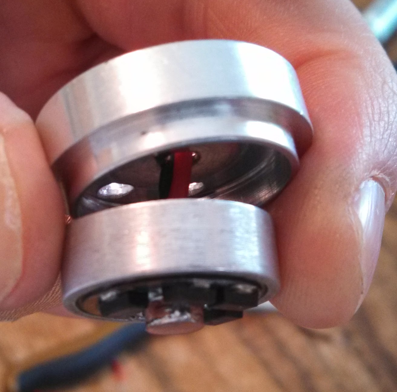
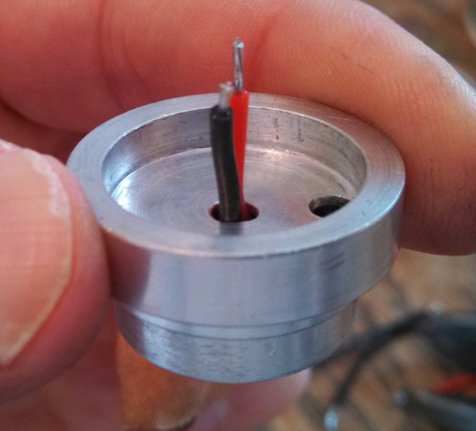
Next, the copper heat sink was coated with thermal paste and slid into the emitter pill while bringing the wires through. The top of the heatsink was coated with a thin layer of thermal paste and the emitter board was wired up.


At this point, I powered it up, got a flicker, then smelled something burning. When I took it apart and examined the driver closely, I realized the 5 stack was slightly raised and a bare section of wire shorted against the bottom side of the emitter pill. In hindsight, I should have covered the chips with Kapton tape to prevent the short. Frustrated at this point, I removed the driver and modded another board with extra chips, but this time I did it the traditional way of stacking. One chip was stacked on top, the other 4 were added to the bottom. Powering up the board gave only 4.22 amps, so clearly one of the chips was not working either because it was not fully connected, or got damaged too much heat. In any event, I wasn’t going to tinker with it anymore since and additional 350 mA was not going to make a huge difference in output.
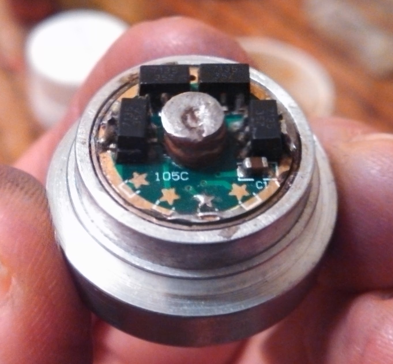

Positive connection was made using a copper contact pad on the driver which is pressed against the bat+ on the switch once fully assembled and head screwed down. Negative contact was made between the driver bat- and switch bat-

Now onto the switch. I did not want to recreate the stock Maglite switch boot, but instead wanted something smaller and more aesthetic. However, I also needed a removal switch boot so I could tighten the allen wrench the secures the switch against the inside of the body tube. To do this, a small hole was drilled into the body just above the switch activator. From my parts bin, I found a small brass cylinder that was the same diameter as the switch activator. I drilled a hole about ¾ of the way into the rod, and attached several mm cut from a wood screw thread using JB weld. The resulting switch button could be securely screwed into the switch activator, but could also be removed when needed. The switch action is nice and smooth, and is easily operated with either thumb or finger. Being a Maglite, it is a forward clicky, so a half press to cycle modes, and full click to set.
Now to tackle the hole in the tail cap that remained from cutting down the body. Using the same method to create the copper heat sink, two copper discs were cut from a flatten copper couple, and soldered together the same way the heat sink was made. The edge was beveled so it would fit snugly into the tailcap, then sanded and polished.


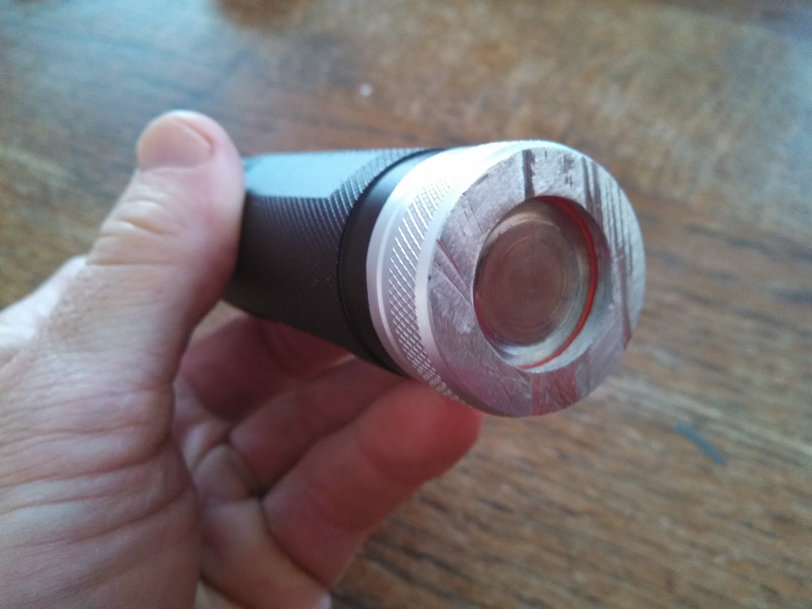
Finally assembly of the head was done by screwing down the optic holder until it was seated firmly against the emitter. Several mm had to be shaved off the optic legs for perfect focus, then the optic was snapped into place. Nothing additional was needed to keep it secured.
Optic holder secured against emitter board.

Optic snapped into place.

After cleaning and polishing, installing O-rings and lubing the threads, the light was complete at least.


This is now my go to light for walking the dogs. It's compact, bright, and fits nicely in my hands.