I have picked up quite some info on the NANJG-style drivers, but all other drivers are mostly a black box to me.
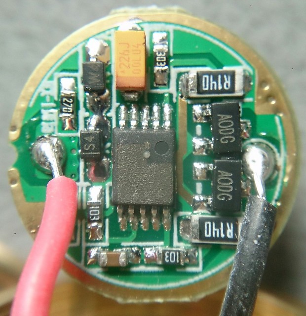
This one has three ok modes (high.medium,low) and no detectable pwm (I really tried!). Can anyone tell me by looking at this driver if the levels are perhaps current controlled, and if the output can be tuned a bit (it is 2.5A now, nice current, but I would like a bit more). Thanks!
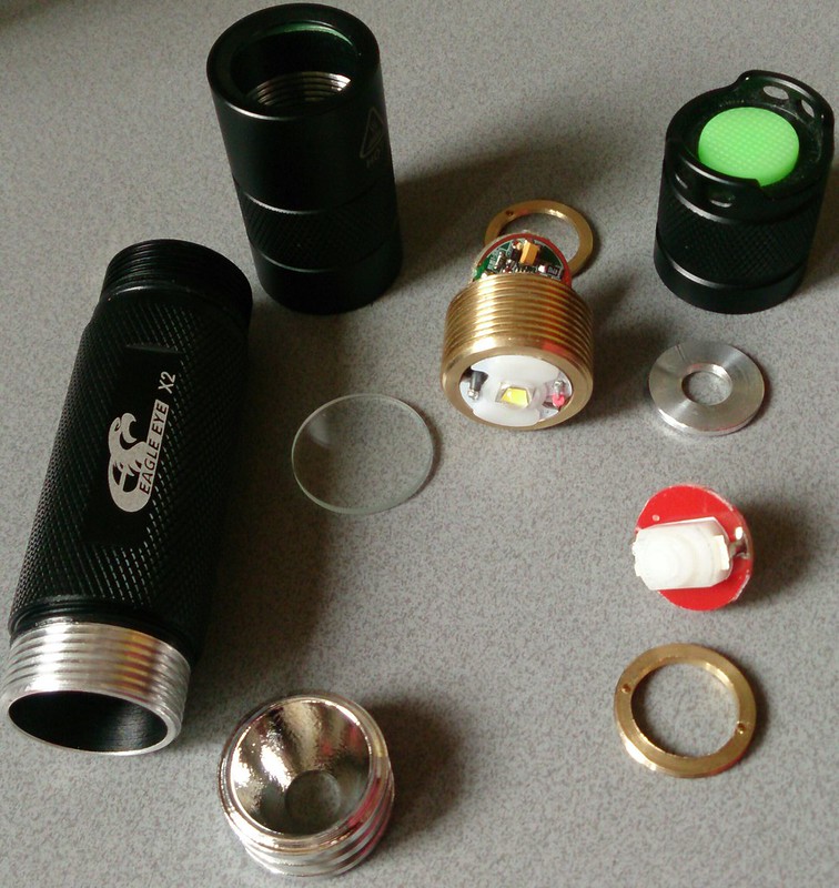
BTW, this Eagle Eye X2 is a pretty boring looking tube style 18650 light, but for the price it is very well build (Convoy level), and very suitable as a host, almost all parts are standard and replacable:
There are two SOT-23 FETs (3-leg things, marked 'AODG') in parallel, and the two R140s are limiting resistors between the FETs' ground pins and the actual battery ground.
Thanks comfychair, so the modes are pwm-controlled with a very high frequency..., or (wishful thinking): high=2 fets, med=1fet, low=a third route on the board somehow. Not likely I know, but I will have a look at if the 'feeding' pins of the fets are directly connected or go to a separate pin on the mcu.
Nope, two FETs for high/1 FET for med wouldn't work. Not enough difference in total resistance between 1/2. The resistance of 1 FET + 1 R140 would only be halved by adding in the second parallel set. If the FETs are really high resistance you might be able to detect a difference in light output, but definitely not enough to be used for actual modes/levels. There very well may be two separate lines going from each FET to two separate pins on the MCU, but that doesn't mean they're being controlled independently.
Ah, well, I will just solder some 0.1 ohm resistors on top of the 0.14 ohm ones then (or just short it altogether), and perhaps reinforce some springs, and wish the fets good luck :-) .
The problem can be that every time the FET is switched on the voltage breaks in, because in this moment there is only the onresistance of the FET limiting the current and this is like a short. This can confuse the controller….remember the issue with the big capacitors…
Maybe instead of stacking use just the .1ohm resistors. There’s probably a point where it stops regulating modes somewhat above stock output. Work your way down in resistance until you find that point.
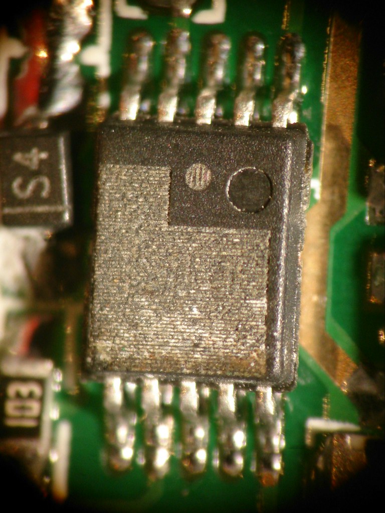
djozz, can you identify the markings that were not ground off of the MCU on the driver you pictured? Between the dimple and the ground-off section there appear to be two circles, one filled and one with a design inside it. A clear picture would be great. I’d like to know what MCU this is.
Thanks djozz, good picture. In post #1 of this thread there appear to be two circles in addition to the circular dimple / depression. Do you agree? Do you think that was a camera artifact?