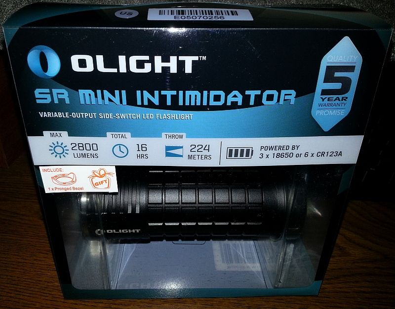
So I’ve been waiting several months for the Olight SR Mini (my first 18650 light!).
It came today!
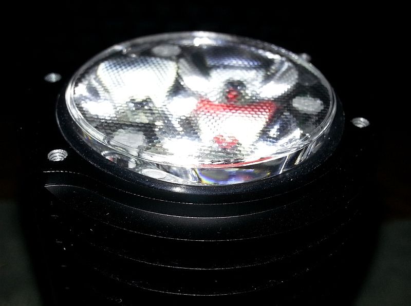
Hey, it even has the crenelated bezel.
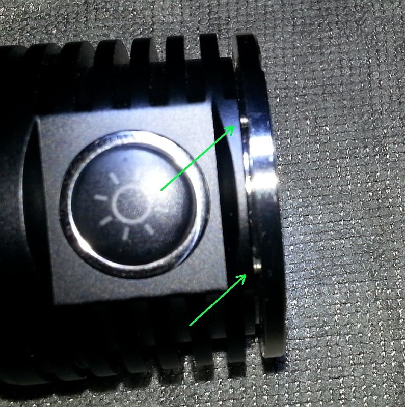
I look it over… fit and finish is generally good, but the bezel doesn’t fit very well:
I’m not too thrilled with the screws spanning the gap.
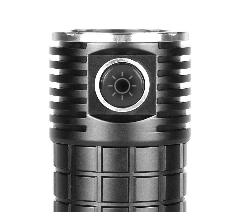
Hmmm… how is it supposed to fit?
A little google action shows this:
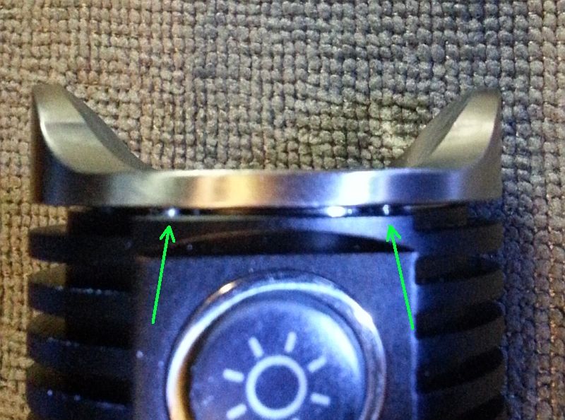
Let’s try the crenelated bezel, maybe it will fit better.
Nope.
OK, maybe the optic isn’t seated correctly?
I pull it up/out, and it’s a touch stubborn as (I find out in a moment) that the switch wire is wedged between the body and the optic (the parabolic part).
What do I find? Nothing that helps me figure out how to get the bezel to sit better.
But I did find a cold solder joint on the switch… it’s really loose
$150 for this (plus another $150 I spent on a couple of 18650s and a charger).
I’m a little disappointed.
Can someone fix the solder joint for me? I don’t have the right tools (or the skill).
The head/bezel… I don’t know what to do about that.
if it’s the wire positioning problem then it’s a easy fix.
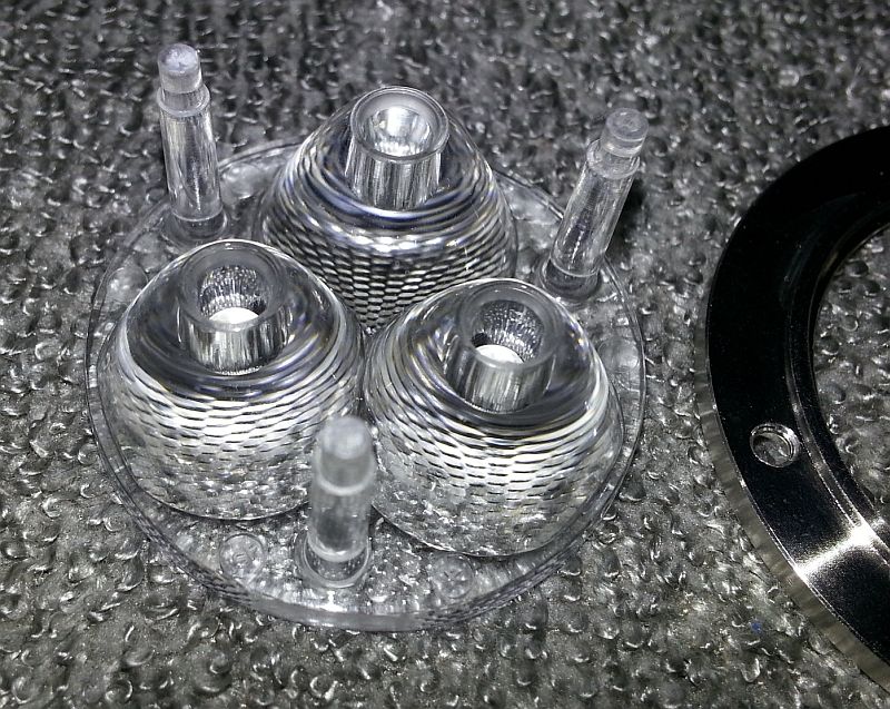
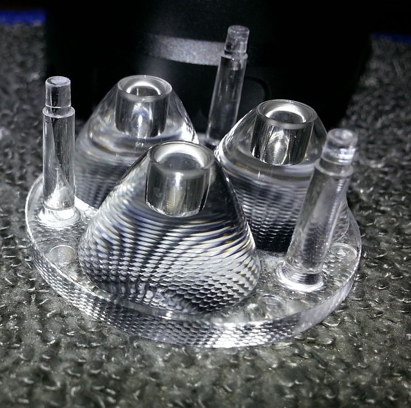
Could you take a picture of the optics but from other (inner) side so we could se how big it is and how much place there is for wires!
That lose wire is really unacceptable IMHO. Doubly so at this price range.
You could take a video showing that the solder joint is bad & its loose. Send it to Olight, tell them you want a replacement and for them to cover the cost of sending it back. Oh, and link them to this thread.
Sorry, your first 18650 light turned up with problems after waiting for it.
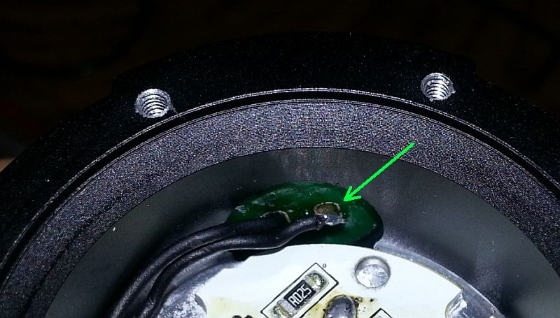
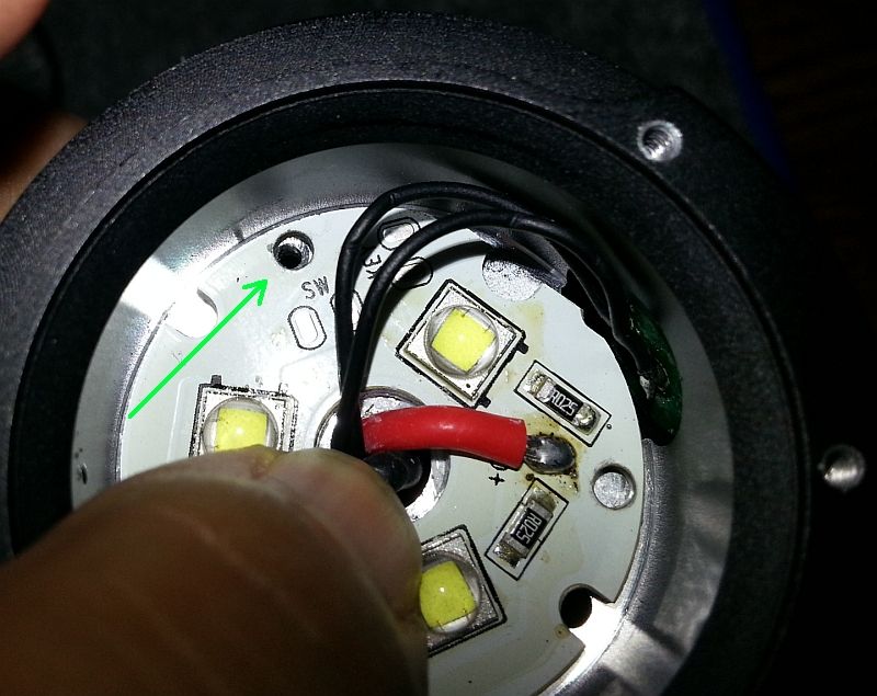
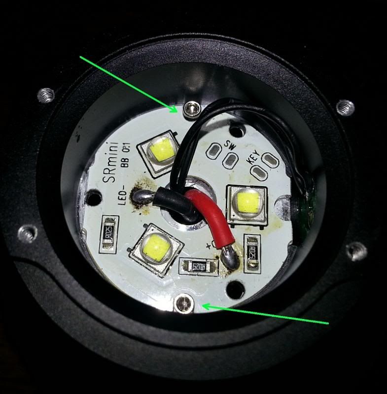
The star flops around loosely, the wires push it up/away from the heatsink once the pressure of the optic is gone.
If I hold the star with my finger, there are some holes that can be lined up (green arrow)… maybe it would have been a good idea to screw the star down onto the heatsink/body.
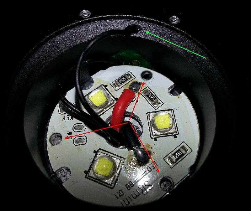
Good idea… as soon as I started recording and barely touched the wire with my finger (green arrow)…
Well, so much for that.
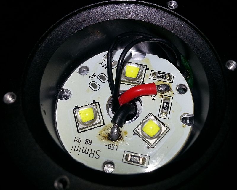
Never mind my comment about screwing the star through the holes into the heatsink (red arrows);
those three holes is where the posts of the optic sit.
I have several of the Olight i3S. It’s an excellent light (which is why I bought a few more of them)!
But this isn’t even a $50 light, let alone $150.
The next time I buy a “premium” light, it will probably be a Sunwayman.
Wow. I would be emailing the seller for sure. That is just horrible. I hope you get a new light. Maybe get Olight to send you a new (better than that) light and refund your money.
I’m glad you showed this. I was considering the group buy for this as I don’t own any multi emitter lights. I won’t be buying an Olight that’s for sure.
Why are there resistors on the LED MCPCB? It looks like maybe the LEDs are all in parallel and they are using the resistors to prevent thermal runaway of any individual LED. If I’m correct, that’s a rather cheesy way of designing the light. It’s always best to run LEDs in series to prevent one from hogging all the current. Running them in parallel with balance resistors will work, but you waste power in the resistors.
Hmm, not sure why they messed up like this, there is enough spacing around the optics for all wires!!!
And I was all like: “Olight never makes mistakes”
I think there might be holes for the optics legs under the LED board.
Try rotating the LED board and see if the 3 holes align. That should allow the optic to go lower and get rid of the bezel gap.
I thought of that; but didn’t want to twist the star too much for fear of damaging the wires/solder connections (especially since I was already having a problem with that). A gentle twisting of the star didn’t give me 3 holes that line up (or even 2 that line up).
I just got a message from Going Gear who are going to let me return/exchange it.
Since it’s going back, I may as well take one more look.
There’s a bit of thermal paste underneath (obviously not thermal adhesive) since the star twists from the wire pressure and is pushed up/off the heatsink once the optic is removed.
Here goes (I give it more oomph since I’m not worried about damaging it anymore).
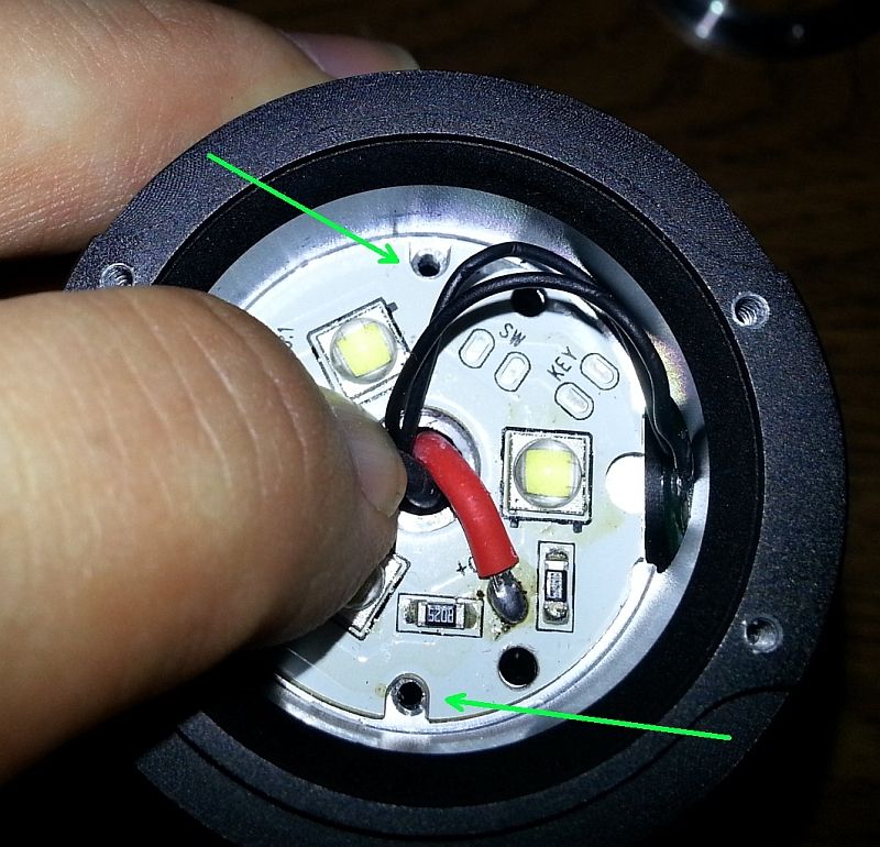
Pressing down fairly hard with my finger, and what do I find… what’s with the two holes (green arrows)?
They look like they’re threaded.
Where’s the screws??? |(
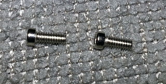
There are 4 screws to hold down the bezel.
They give you 4 more with the “gift” (the crenelated bezel).
Well, since I have spares (and they look about the right size too)…
Let’s try:
Well, this picture says a thousand words, doesn’t it?
This would make for better heat conduction between the star and the heatsink.
And how about those 3 holes that line up nicely… now that the star is secured, if you switch the bezels, the optic won’t push up and rotate out of position.
Screwing the star down would also keep it from possibly ripping the switch wire off.
Olight, I think you forgot something.
Ok, we know what comes next:
Well how about that.
Moral of the story; if you buy an SR Mini, take the bezel off and check to see if they remembered to screw down the star onto the heatsink.
Thanks everyone for the tips!
BTW, I would say that they didn’t planned direct switch connection, there are pads on the mcpcb that were, I would say, intended for connecting the switch and in that case wires would not be problem:
Very interesting. I have one of these about to be on it's way to me for review. I look forward to dismantling it and seeing how it's put together.
If those aren't balance resistors on the MCPCB I wonder if they could possibly be the sense resistors just in a different than usual place. Sense resistors are usually right next to the positive wire on the driver and then straight to the LED. It could be possible for them to have located them on the MCPCB instead of the driver. There is no reason why it couldn't be done this way. If it was then it makes it dirt simple to do a resistor mod and bump the LEDs from 2.8A each to 3.6A each like Vinh does on the MiniVN.
If they were sense resistors, there would have to be a feedback connection between the LED and resistor. The driver has to have a way of reading the voltage developed across the sense resistor.
you should contact the seller or even Olight about the issue. Olight is known as a good brand, and all the Olights i have are very well built with no problems. They should fix the issue for you or off some reimbursement.
OK, I do sort of agree that Olight should compensate me for the postage to send it back (which I’m paying for).
And could I pull out a soldering iron and reattach that wire? Sure… hopefully without messing anything else up.
If the solder repair doesn’t quite work out, then I couldn’t return the light as it won’t be in “new condition” anymore (Going Gear said it has to come back in “new” condition for them to exchange it).