Done the easy way.
I’m starting with one of these, most everyone knows about them.
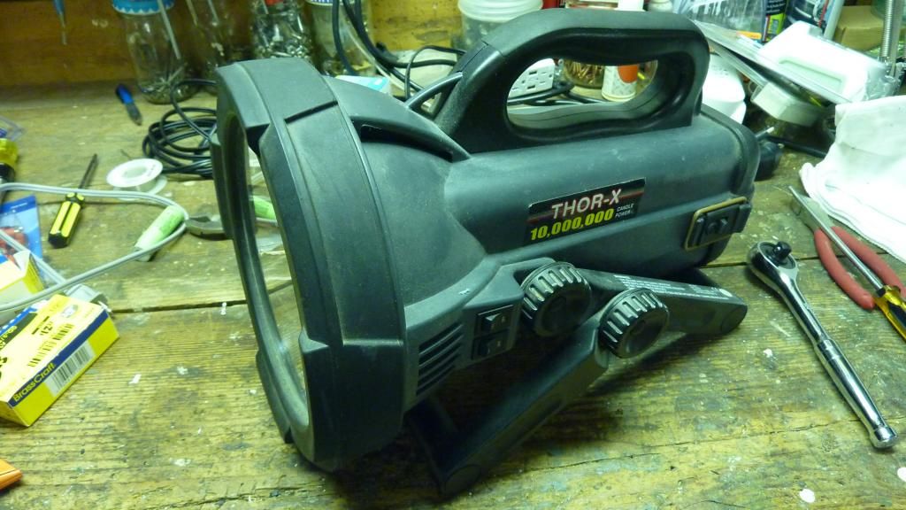
Back probably 10 years ago they were about the brightest light one could get in the mainstream retail channels. I remember my local Sams Club had them on clearance one day and I bought a bunch because the price was very low, something like $10 or so. I remember their regular price was about $30. What I didn’t know at the time is that the 12V rechargable battery that ran them, which was included, was of the SLA type. That type of battery is of the type “use it or loose it” That’s why Sams Club was clearing them out. They were getting old already. Well the ones I didn’t use, I lost. They went dead with no way to revive them. One of the lights I even upgraded by changing the bulb out to a Sylvania Silver Star. It was a little brighter and a little whiter. Hot stuff for me back then.
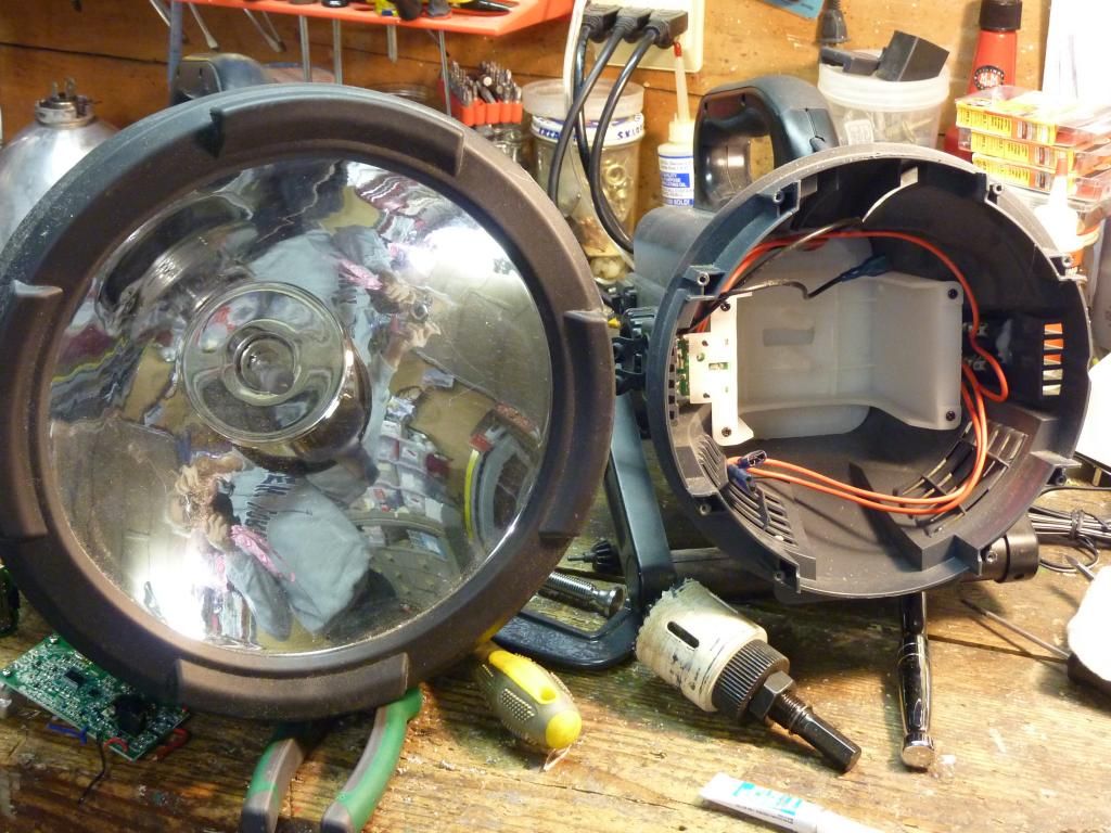
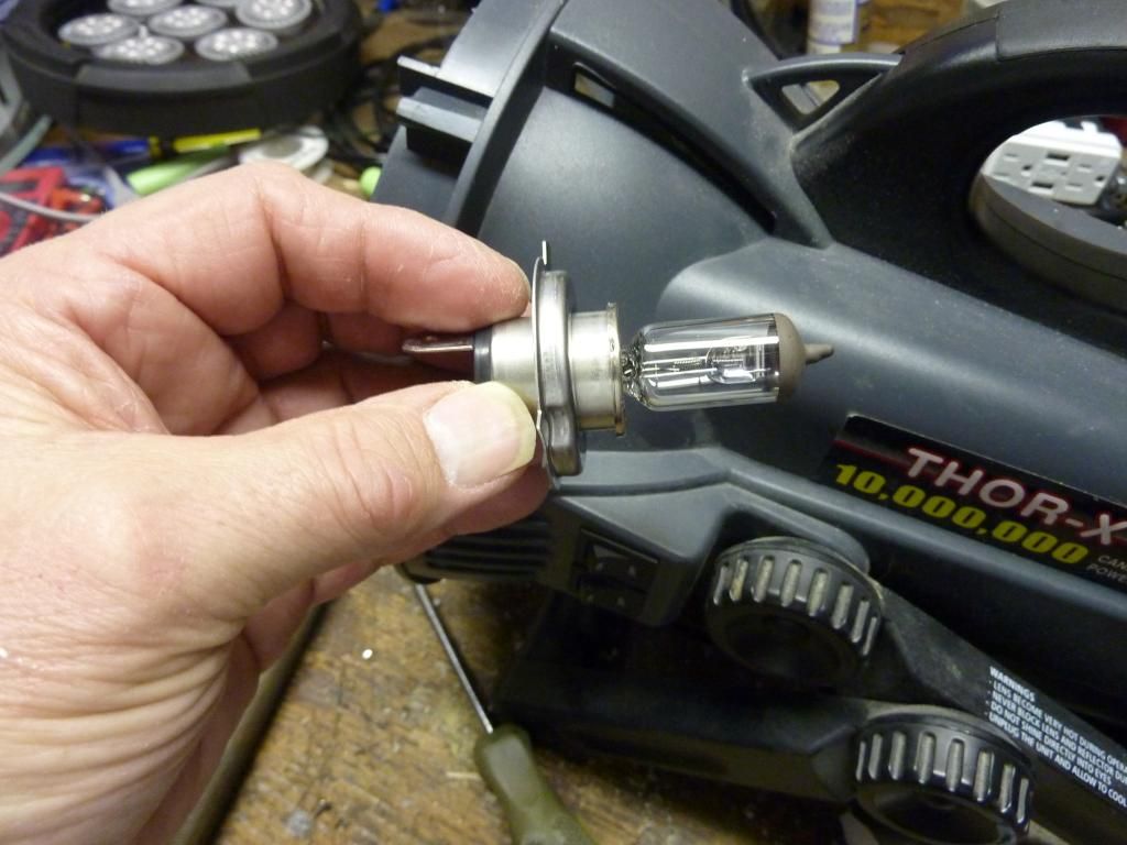
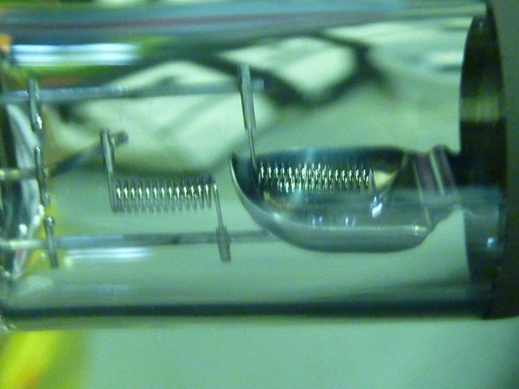
The original lamp and reflector. This bulb draws 10A off that 12V battery.
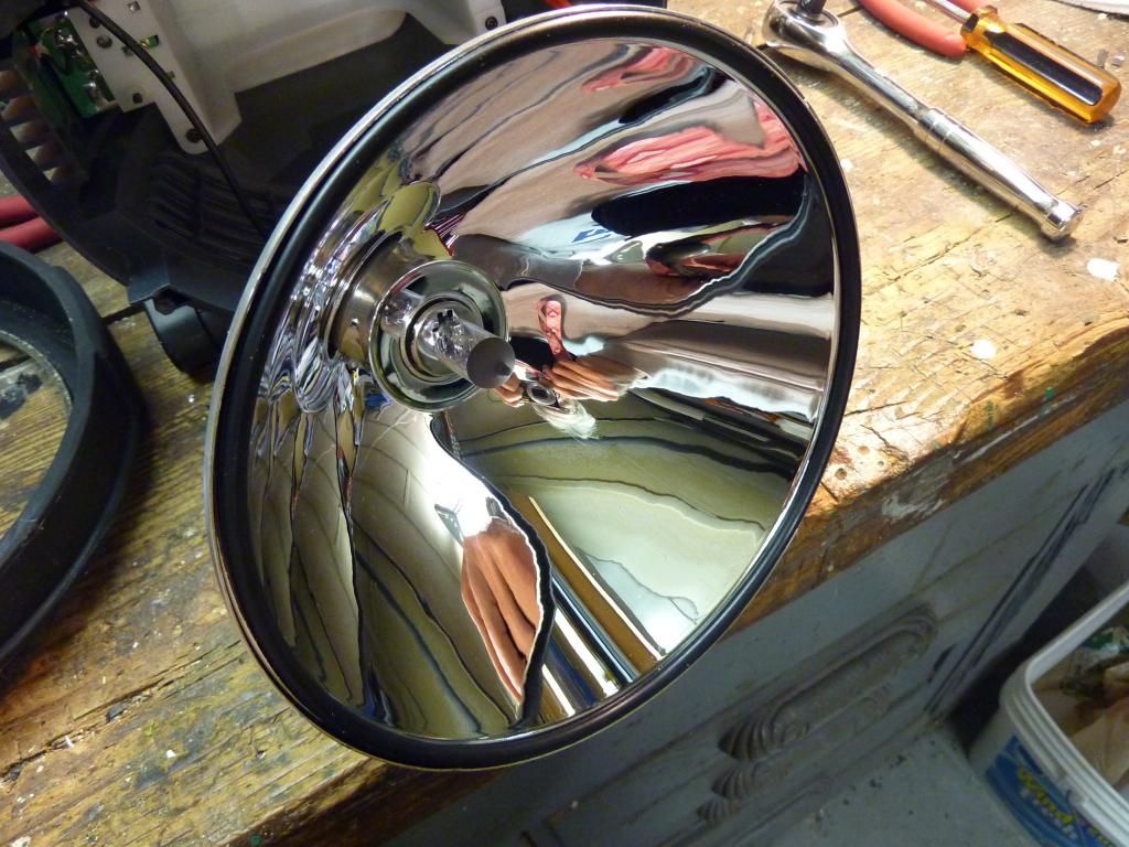
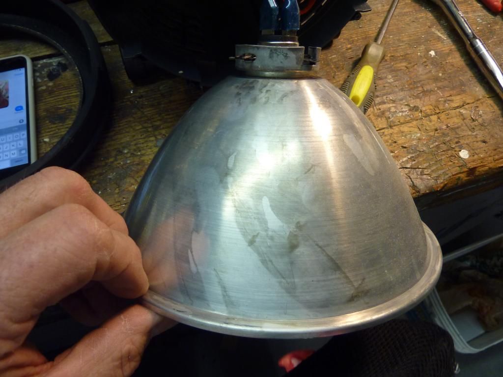
The original reflector is made of aluminum, I will not be using it.
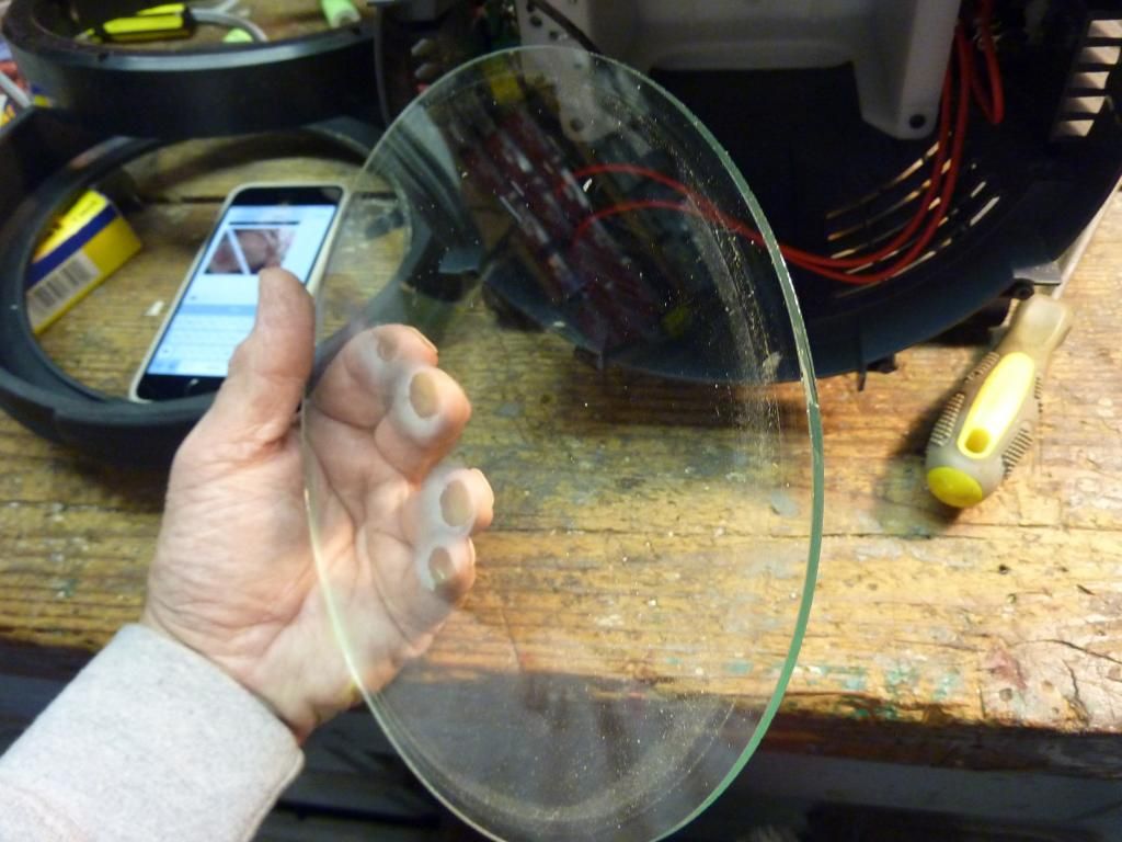
The original lens is made of glass, I will use it to trace out an acrylic one.
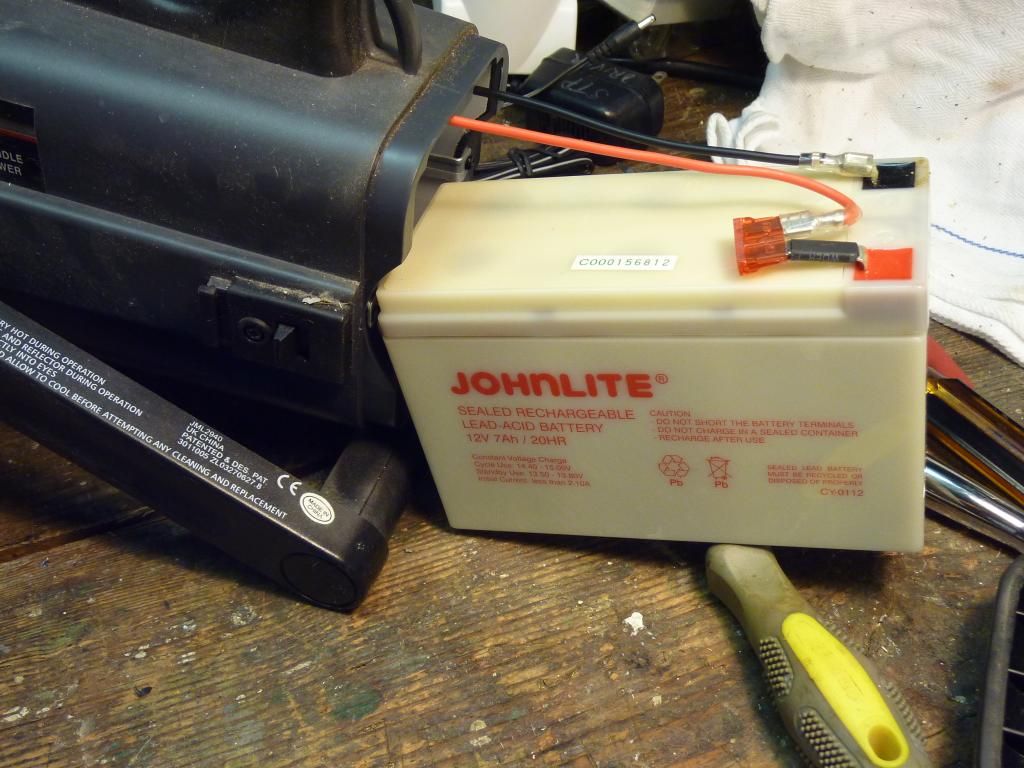
This battery is still good, 12V and 7Ah. I will use this battery at first, only for test purposes. I have a plan to use 18V drill pack batteries eventually.
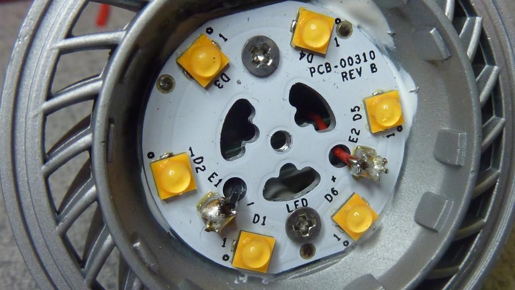
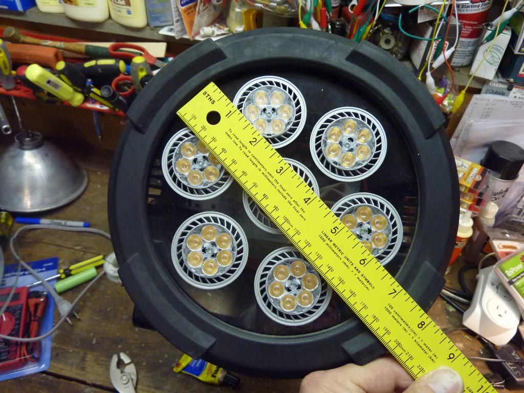
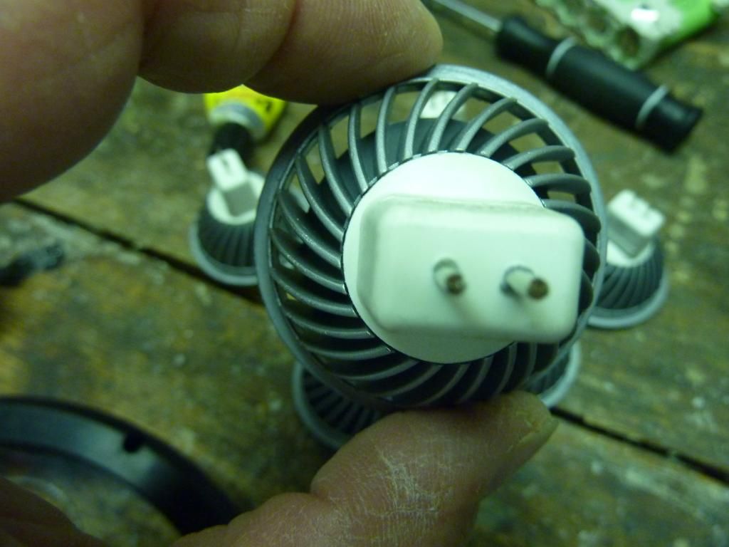
I will be using 7 of these MR16, 12V bulbs in this mod, I posted a tear down and tests on this bulb here.
Tear down of a better quality MR16 LED

Each bulb contains 6 Cree XT-E’s
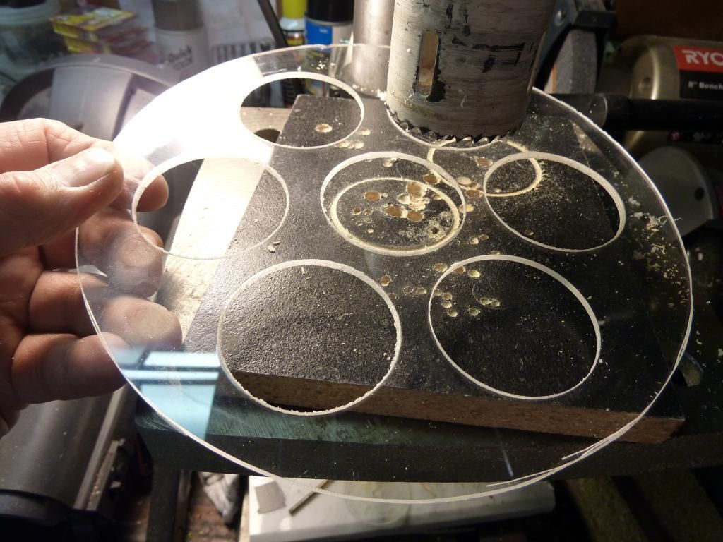
This is the Acrylic lens that I will mount the MR16’s to. I will simply glue each bulb in place.
Tomorrow I will wire up the LED’s and hook them up to the original 12V battery, and if all goes well with that, I will proceed to the next step. That will be installing the Drill pack batteries that I plan to eventually run this light on. That will have 3 benefits.
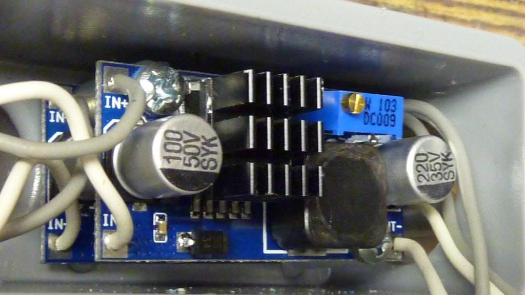
More brightness as I will be overdriving the bulbs with higher voltages. I have some constant voltage drivers that I plan to use to drive these bulbs at around 15V.
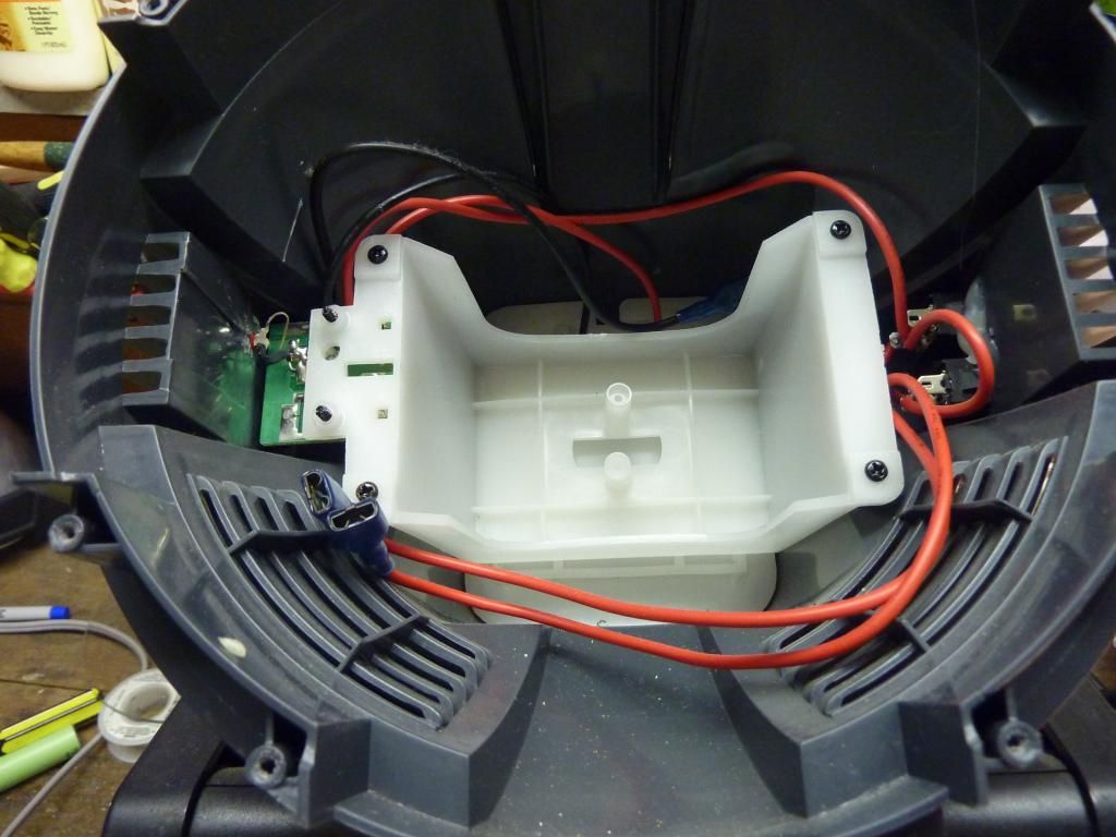
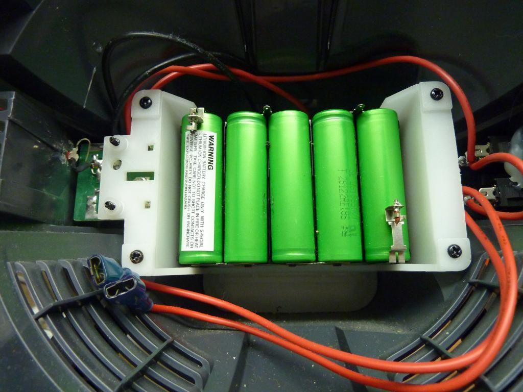
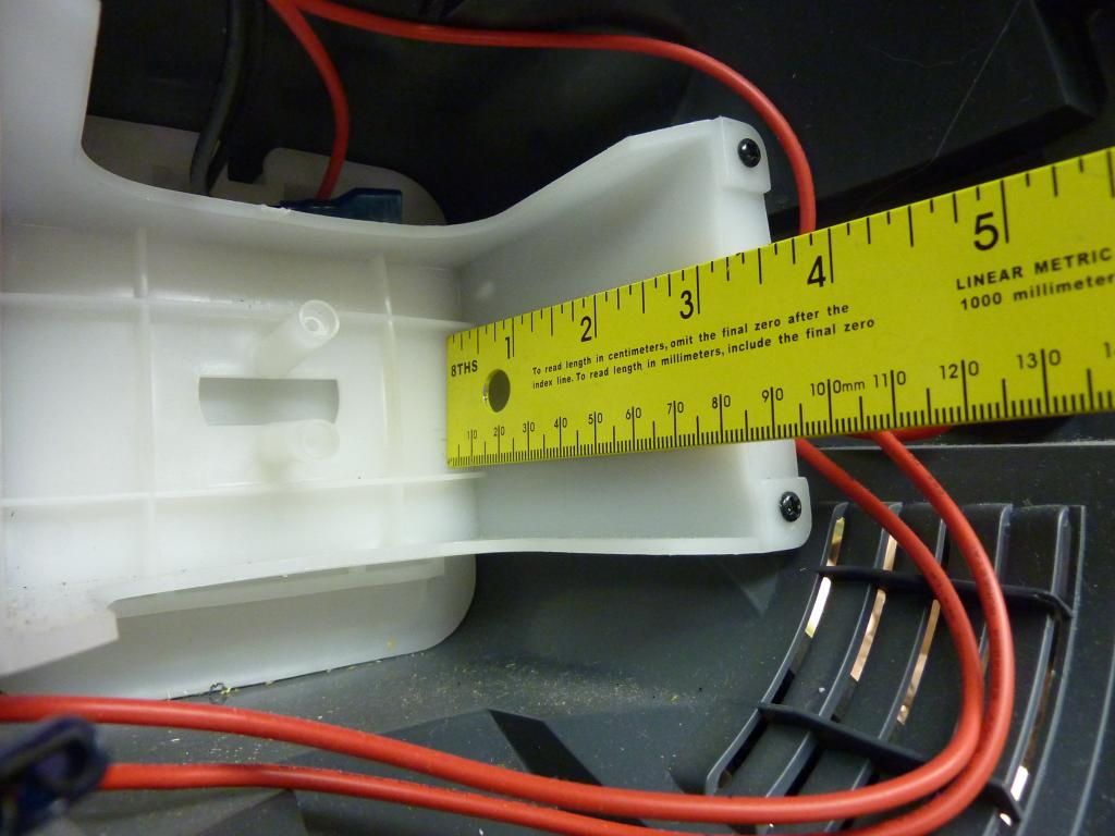
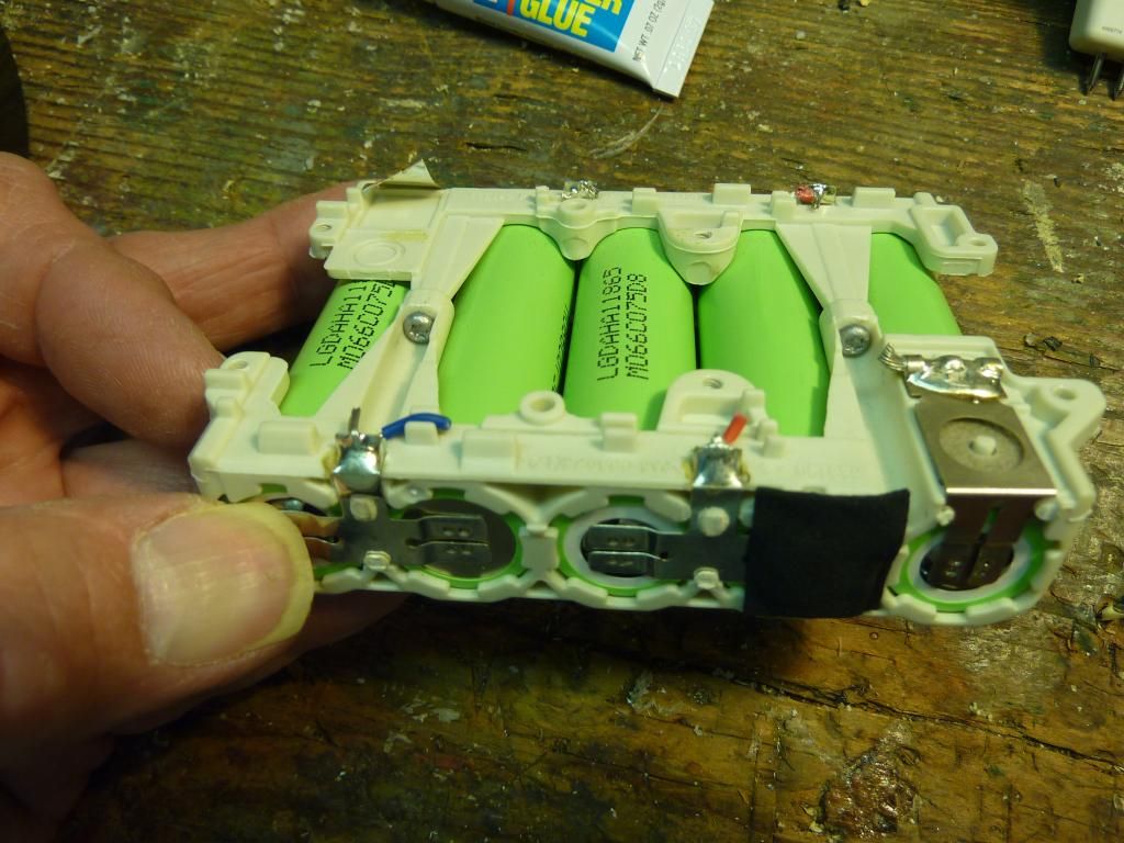
This nylon structure was already in the light, and it looks to be about the right size, so lets use it as a Li-Ion battery pack holder.
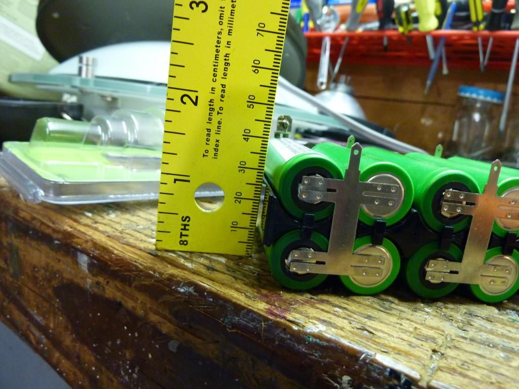
These cells came from a brand new PortaCable drill pack I found in the recycle bin at a Lowes. The onboard BMS circuit board was faulty so Lowes threw it in their recycle bin. The cells though are perfect, sitting right at 3.6V when I rescued them.
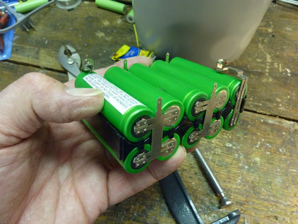
Those are 10 Sony 1500mAh cells IMR. Actually I don’t need IMR’s for this light as the current draw will probably be mosest at around 6A. That could be delivered by ICR’s in a 5S2P config for about twice the run time as the IMR’s
Anyway, they fit perfectly. How’s that for luck!
I think I may be able to stack 2 of these packs in there.
To charge these packs, I plan on using a BMS circuit board from a Ryobi drill pack and mount that in the back of the light.
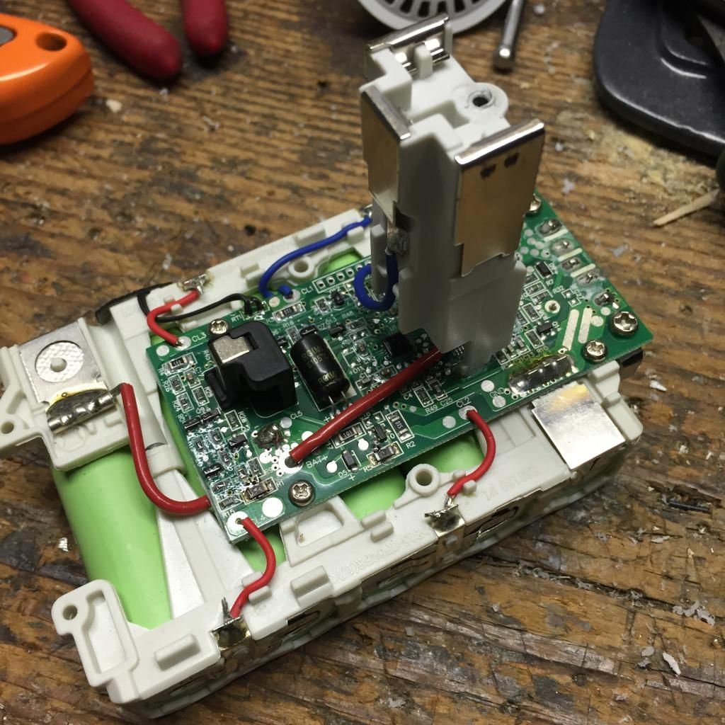
The BMS separated from the cells.
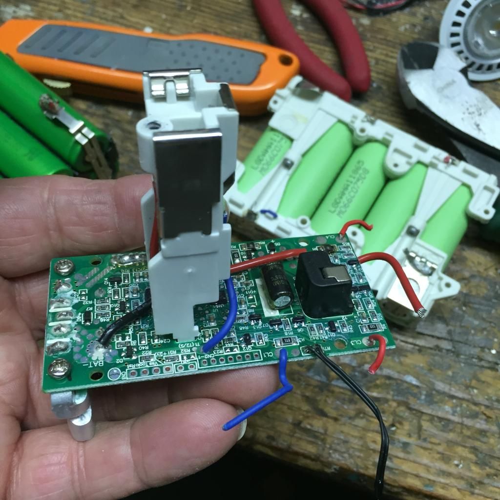
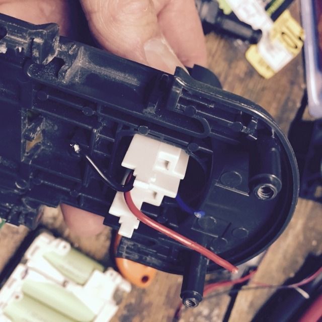
The charging header separated from the BMS
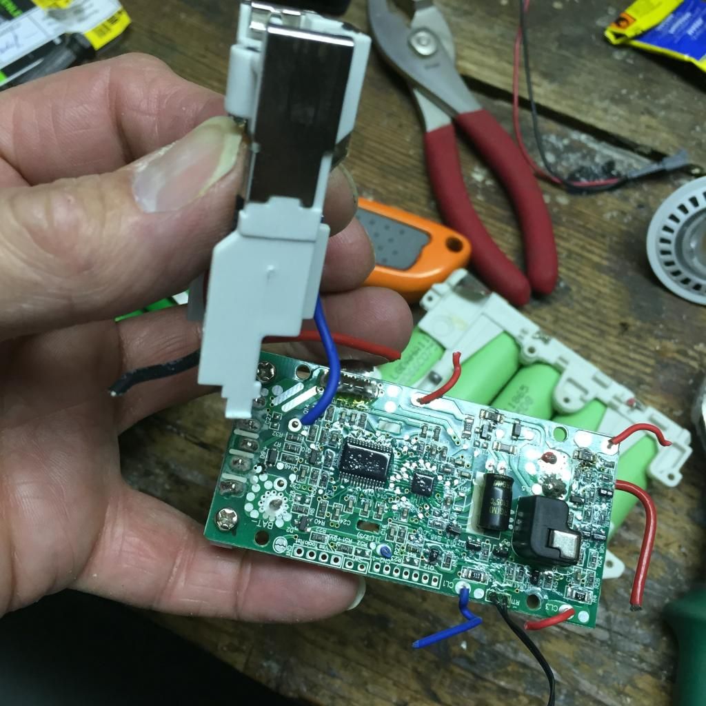
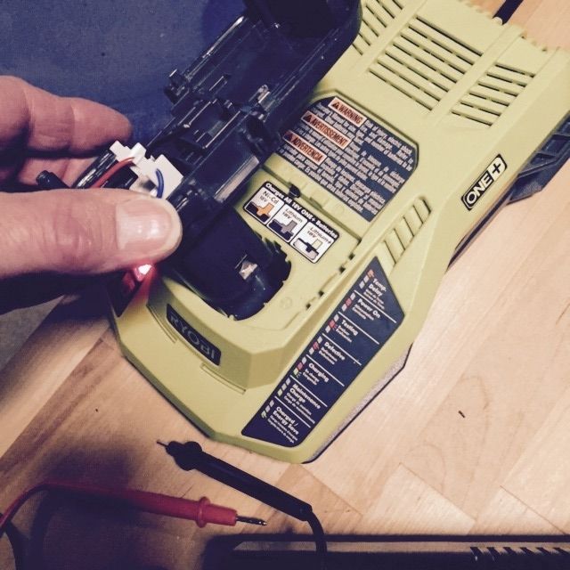
Then I will connect longer wires to reconnect the header to the BMS board in the light so that I can charge the cells remotely with a Ryobi fast charger. This charger can charge a 3Ah battery pack in 30 minutes.
Of this build, I am most excited about the idea splitting the BMS and charging header off from a drill pack to enable fast, safe and remote charging of a high power battery pack. It could change how we do things in the future.
BTW, there are a couple of things I forgot to mention. There will be active cooling, this is a must.
Secondly, I am hoping all goes well as this guy has a big brother. ![]()
Impressive
I’m guessing also very cost effective
Orsm build and very creative. That is one very large light.
![]()
subscribed!
subbed also, gonna get HYPE for this when its done!
Please let us know how much the final tally is ![]()
WOW! :bigsmile: Great project.
Nice build again with great documentation! I will follow this. :-)
Awesome build.
Amazing work, Looks like everything sits in perfectly. GL Looking forward to the finished product.
Impressive build, thanks for sharing!
Do you plan to actively cool the LEDs?
Wow! I actually bought a defective one just like that for about 25 cents, I was able to revive it. I
actually love it as it is. Unfortunately, the battery leaked and corroded the circuit and the bulb. I
felt sad. The worst part is the bulb is rated at 6v, so hard to find 6v peanut bulbs.
its so nice when you see the luck help you in the projects like this. nice idea and it looks like everything is going well. thanks for sharing.
I think most of already know, this light will be a flooder. Also warm white. If it is too warm, I may have to add some more emitters later in cool white. I can see it coming already. I will be tinkering with this thing for a long time. Adding Volt and Ammeters, other emitters etc.
The trouble with these builds is that it is impossible to anticipate the final build cost ahead of time.
Already I have had to get another $1 tube of super glue. I didn’t see that coming! ![]()
Well then, you have the perfect host for a mod of some sort.
BTW, i realize that other members have put together some really unbelievable mods in the past. Probably way beyond the abilities of most of us here. This build like others that I have posted about only require very limited knowledge and skills.
I am presenting this build primarily to the unexperienced builders on the forum. We as forum members must always realize that every day new members join that are just starting out and I think it is a good idea to have simple build content for them to see.
I also am aware that there are other, more advanced members that want to see something more advanced. That’s why I want to show and evolution of difficulty in this build. First a simple build using the stock 12V SLA, then a progression to Li-Ion.
Something for everybody, although the final complexity of this will fall far short of what others have done here.
Ervin, you blew us all away with your scratch build thrower project. Unbelievable what you did with basic tools and materials.
I have always gotten a big kick out of repurposing items and material and tools. That is, using them for things other than what they were intended.
There is a saying here in America, “If you can’t be good, be lucky”
In my case that seems to be true more often than I deserve. ![]()
![]()
![]()
Whoa, 7 of those modules. Sounds just awesome. Should really light up a big area very nicely. Didn't those have a pretty decent CRI rating too?
Is the cooling air going to excape through the led modules?
Loving how you have planned and are documenting this so that the average joe can replicate your build. Very 
no comment subscribed!
I haven’t decided if the cooling air should be drawn into the light and out the back or the other way around. If there was a lot of heat I would think that it would be best if it was kept away from the batteries and electronics. Even though there will be a lot of heat, in relative terms it won’t be that much and it takes a surprisingly small amount of air flow to effectively cool these units. I think these modules are gorgeous in their looks and design. In fact get a load of the curved fins on the heat sink. Turbine like blades and were probably designed that way to aid in the convection air flow that these units normally would rely on to keep cool. It should not take that much active cooling to do the job effectively.
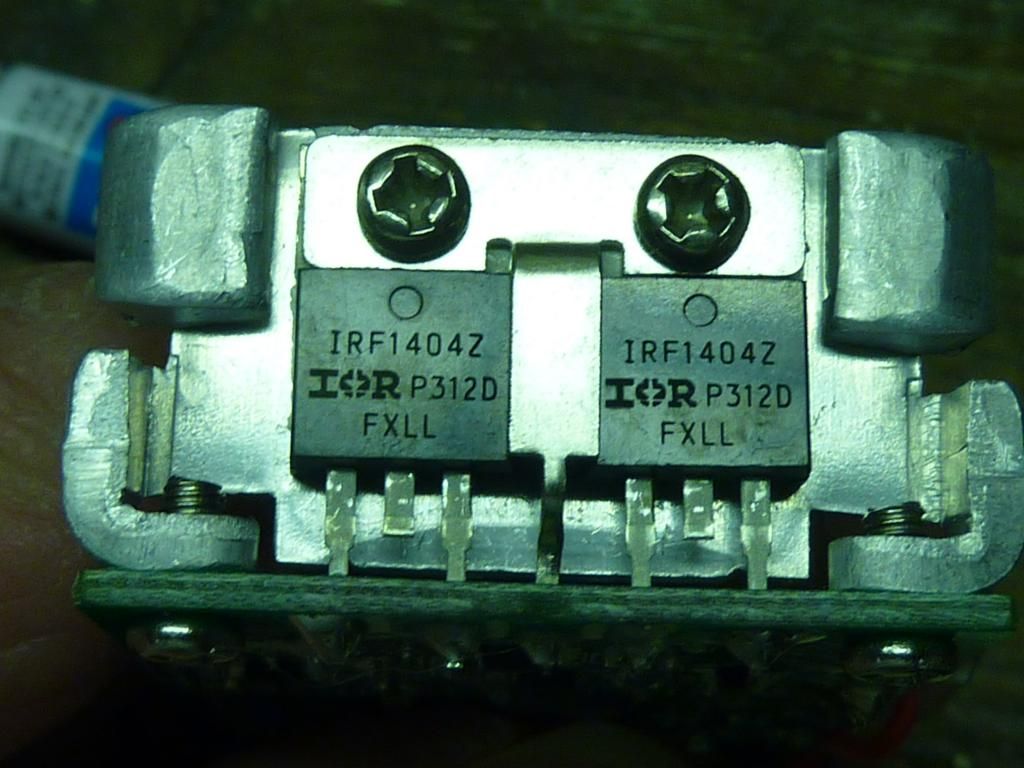
While the glue is drying, I thought I would point out how many useful parts there are in an expired drill pack. They can be found in the battery recycle bins in lots of home stores. Even though I will not be using these cells in this light, those 2 screws would allow me to take this apart and either the cells or the holder could be used for something else.
Each of the Ryobi and Ridgid drill packs have 2 high power FET’s. In this case 2-1404’s. These FET’s have a much lower gate resistance than even the 70N02, which is no longer available. What I understand though, is that the output levels of the MCU’s we use are not high enough to turn one of these on. Back in the days of discrete components a buffering transistor would be used to increase the signal level. For example there is the zener mod (discrete component added to a driver) to enable the MCU to operate in a higher voltage light. Maybe something similar could be done with one of these.
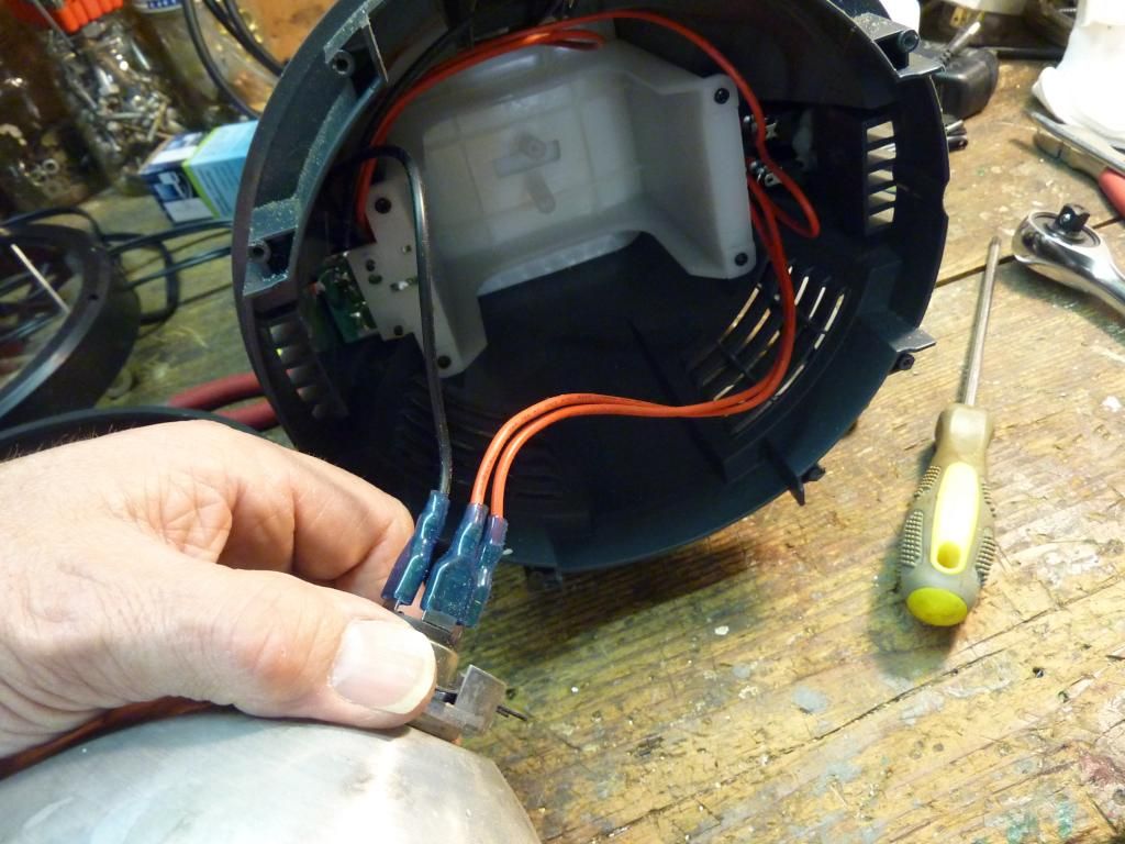
When I wire this light up, I will take advantage of the fact that the original light has 2 switches. One for “high beam” and one for “low” The original bulb, an automotive type, has 2 filaments. That means either or both can be switched on.
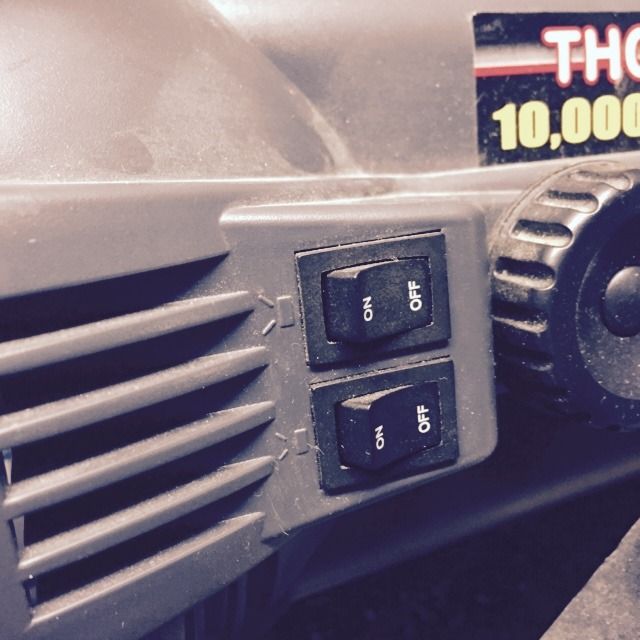
I will connect one switch to just 1 of the modules and the other one to the other 6.
BTW, these modules are rated at 525 lumen each at 12V. From charts of the XT-E and the current that flows through them, I am thinking that those 525 lumen is OTF. Also, I would think that is how they would be rated anyway for the use by the general public.
I have already tested these at higher voltages and they do produce considerably more light when over driven.
nice giant build ! ![]()
I did a mod with this host and I installed fans. You can see the pics of it here. The fans are 40x20mm, 8200 rpm 12v fans and are said to produce 10.8 CFM air flow each, at 27.5 decibels.
Courageous mod by the way! I wonder if it will project much of a beam.