I have 6 of them, 2 from an early batch, 4 from a semi-recent purchase. They all fit fine in my L2 and L6.
I’ve read some people find they are a bit short for their L6. Adding a small solder mound or attaching a ~4mm magnet should fix that if it happens to be an issue.
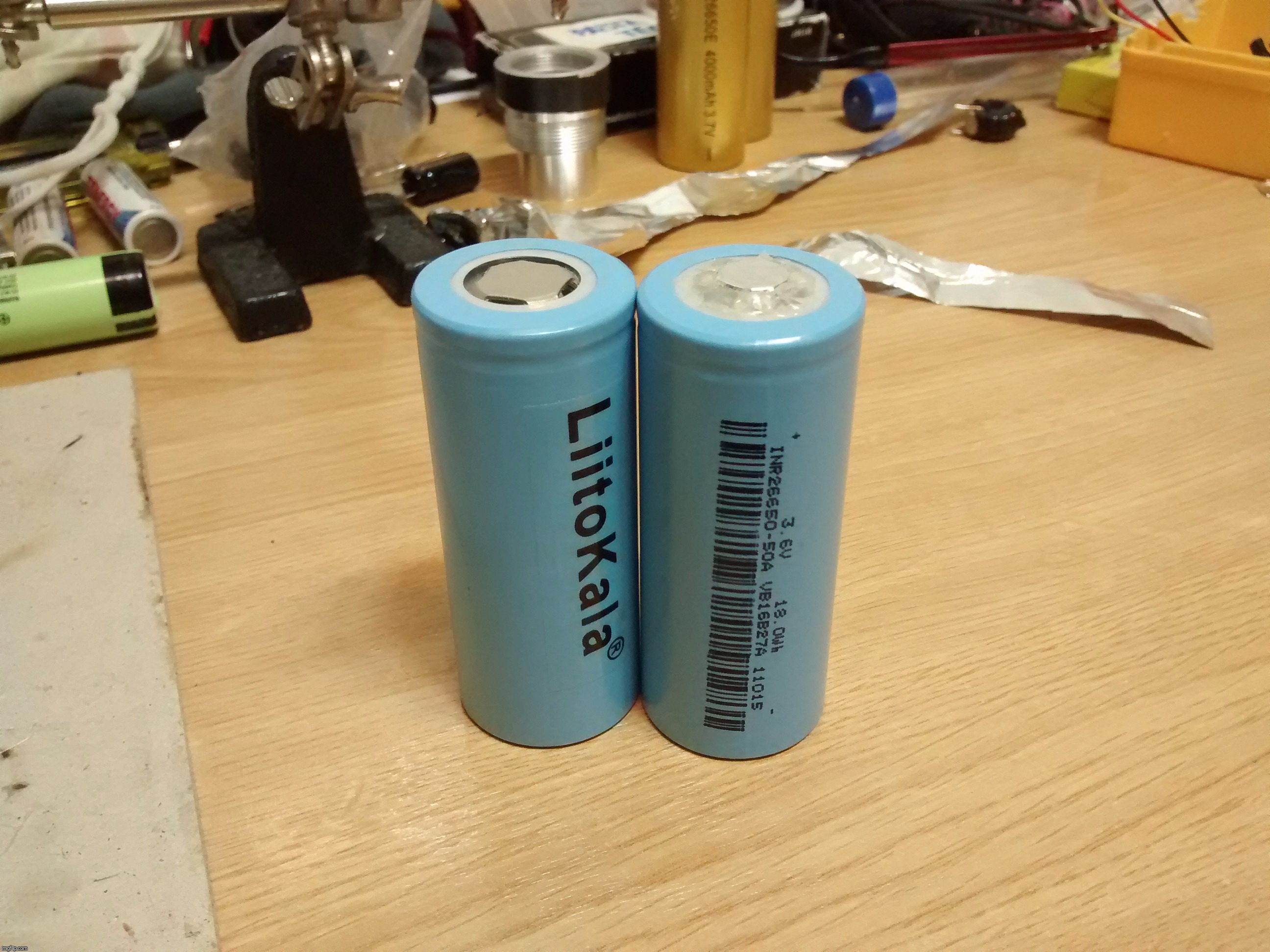
Yep, liitokala 26650s fit fine in the L2. They are a bit wider than most cells; it’s almost a “vacuum fit”. Dropping the cell in the tube results in a slow fall due to the air pressure.
You will probably need to add a button top to one of them so they connect in series.
At 0.667 × 10⁶ S/m NdFeB's conductivity isn't very good (source: e-Magnets UK). Close to 1/90th that of copper (copper conductivity is about ≈59.6 × 10⁶ S/m). However, since you're only going to use a thin disk of it, it's quite unlikely you'll run into any sort of issues. Anyway, do yourself a favour and go wide with them. I have ∅8 × 1.5mm magnets, they're useful for lots of things. With such diameter (50.2655mm2), they're tantamount to an AWG20 copper wire in conductivity (a tad better in fact).
I have posted elsewhere that I found that neodymium magnets reduced current by nearly 0.5A when used to connect 2 x Liitokala 26650”s in series.
This was in an S70 on turbo & was tested on the same cells with magnets against solder blobs.
Due to this I stopped using magnets & now solder blob any flat top cell to make contact in series.
Maybe my magnets had high resistance & others are lower, I don” know, but because of this I stopped using magnets.
Would you mind trying them fully charged & in series as I definitely saw a drop of 0.4 something amps when in series on a tail cap amp reading in an S70 on turbo.
I tried this with several cells both with magnets & solder blobs & got the same results.
As I said perhaps my magnets had high resistance & I agree that the difference in your tests is not worth worrying about but a 0.4A plus drop was to much as far as I was concerned.
Don't freak if they're lower N grade, they may exhibit a lesser pull force but at the same time they're more temperature resilient, which may be preferable.
Right cell with aluminium foil wrapped disk magnet and hot glued by the sides.
In all honesty, after taking another peek at the K&J Magnetics: Temperature and Neodymium Magnets article, I've noticed the permeance coefficient curves for N50 grade magnets look abnormally good, at least compared to its cousins.
The magnets I bought are holding 6 × 5730 30mm led boards over an iron lamp jacket, 2 on each. Since the emitters don't go above 60°C, I think this is the main reason this is working well and they haven't fallen over my head.
It's an interesting read. If you need your magnets to stay in shape at higher temperatures, the advice is to go thick with them (high permeance coefficient).
I explained above that a ∅8mm NdFeB magnet's conductance is tantamount to ≈0.562535mm² of copper (AWG20 is 0.518mm²). Conductance (“G” magnitude, unit S, siemens) is the inverse reciprocal of resistance (“R” magnitude, unit Ω, Ohms):
S = 1 / R, SR = 1 = RS, R = 1 / S, R = V / I => G = I / V
Cheers ^:)
P.D.: you're unlikely to incur in any sort of performance bottleneck because of using NdFeB magnets for battery interconnections.
Interesting question with the magnet and fairly easy to answer (At least for me).
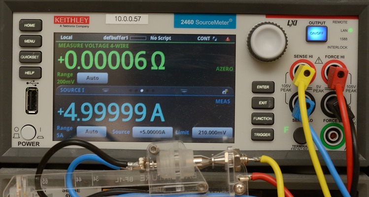
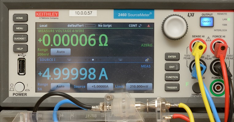
I checked two magnets, both about 1mm thick, one ø8 and the other ø12, both are cheap magnets from China:
The above do not include any contact resistance or cable resistance, only the resistance of the magnets!
According to ElectroDroid Android app, 34.346μV drop on a 1mm long bit of AWG20 copper wire when 1A of current flows through it, corresponding to a resistance of 34.346μΩ.
Is 12μΩ what I can infer from your measurements, HKJ? If so, it's actually a tad better than expected, at least for the ∅8mm unit. And nothing to worry about, it seems.
Cheers
Originally posted on Fri, 04/07/2017 - 15:29; edited to add missing “… when 1A of current flows through it…”.
.jpg)