Taking all of my inspiration from dorpmuller's (aka Rich's) Super Mag build, I decided to do my first rather expensive build. Be sure to check out Rich's build if you haven't, as I have a lot of respect for the wiring he did after putting mine together (and mine is much simpler!). My goal was run run 3 x XM-L's without having to run Li-Ions in series - I'm still too scared to go that route ;)
Here are the parts I purchased:
- 3C Maglite (Amazon.com)
- 3 x Ledil Boom reflectors for MC-E, 20 degree spot (Digikey.com)
- 3 x Cree XM-L neutral-white star (Ledsupply.com)
- Perfect Tri-Start (PTS2) heatsink for C mag (Sandwich Shoppe)
- UCL lens (lighthound.com)
- 26650 IMR battery (TacticalHID)
- 8x7135 driver board, and 4 4x7135 slave boards (illuminationsupply.com)
- 20 and 22 gauge silicone jacketed wire (epbuddy.com)
- Deans Micro Plug 2R (local hobby store, can be found on epbuddy.com as "micro connections")
My goal was to hit 2.8 amps per emitter, so 8.4 total, using just the IMR battery. Having not heeded Rich's advice, I can only get 5.5 amps max on the IMR. With all of the wiring there must be too much of a voltage drop. Using 4 Tenergy Centura nimh batteries gets me to 8.4, but I haven't tested it for more than a few seconds.
First I modified the stock Mag switch to prevent it from messing with my multi-mode driver (just google the C mag switch and you'll find more info about it).
Then I connected all of the driver boards. I could have just purchased 3 x 8x7135 boards, but this was slightly cheaper and I didn't feel like wasting the extra attiny13's by having to remove them.

Then I worked on mounting the LEDs
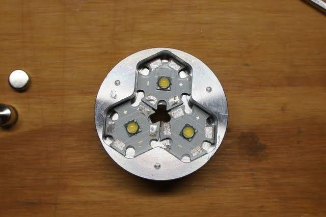

Then I had to grind away at the bottom of the reflectors to get them to fit with the wiring.

I glued them down with super glue making sure NOT to touch the LED dome. Of course it pretty much set instantly, so two of the LEDs aren't centered perfectly but I'm too lazy to redo it.

I sent the Mag C tube out to Jesus from CPF to cut down and re-thread it to fit the 26650. I didn't want to pay him an extra $25 to bore it out to fit the 26650 thinking it would be easy to do on my own. Well, it took me hours. Since Dremel bits aren't long enough, and I couldn't find a cheap sanding drum to mount on a drill, I just made one myself. I basically took a bit extension, wrapped it in tape, then using tape wrapped sand paper around it. It wasn't until after inhaling a good amount of anodizing and aluminum that I came up with the ingenious idea to mount the hose from my vacuum behind Mag tube as I bored it. After test fitting, sanding, test fitting, sanding...the IMR finally fit.

Now I went to town on the bezel (another pain in the ass). To get the anodizing off I ended up taking my wire wheel to it. After that I various grit sand paper, a file, and my Dremel sanding drum to make the notches. It's not perfect, and I haven't even put clear on it, but I like the way it looks.


The sink is meant to thread into the head, but this left too much of a gap between the reflectors and the lens. Plus, threading it down in the head, no matter how I look at it, will cause the wiring to get all twisted up. To fix this I just found some stock washers at the hardware store -- they worked perfectly! Now the lens and bezel hold the drop-in in place.
Here is the MESS of wiring. I normally sink my driver boards, but in this case:
1. I didn't have the room
2. I wanted to have access to the attiny13A microcontroller so that I can flash it with new programs if I develop/find a better one in the future (or if I want to change up the mode sequence, brightness, etc.).
That exposed wire is just the ground wire, so if it comes in contact with the body it's alright. I actually used gray automotive RTV to hold the drivers in place as DX never wanted to fulfill my order for Fujik thermal compound  . You can see the Deans Micro Plug there too which actually worked out really well. There might be a slight voltage drop across it, but it's nothing compared to the JST connectors that I tried out from EP Buddy -- they just had too much resistance causing the amps to drop down around 4.5.

Anyways, my next step is to have Jesus cut down a 4C Mag tube I have sitting around to turn it into an extender to allow me to use 4 x Nimh batteries when I really want to push it :)
So far I'm really happy with it, even though this light is all about flood when I really enjoy lights that throw. It really is a yard sweeper as it lights up my entire back yard while still getting a good amount of distance. This isn't something that I'm going to be keeping in my glove box, junk drawer, or night stand -- it's really just a fun light to have around to either impress fellow nerds, or make my non-nerd friends shake their head at me :)
- Jon