When I take tailcap current measurements I can get the current to vary greatly depending on how soft or firm I press the probe against the battery. If I compress the +B spring all the way flat I can measure current gains of up to ~1-1.25A (depending on the light and cell used).
I think the additional resistance comes from the cheap +B springs used by the manufacturers. Would a low resistance mod (copper braid) benefit the lights that exhibit this?
I am so glad somebody brought this up. Would like someone smart about this to tell me how to do it. There are a few lights I have that I can vary the draw by a half amp just by pressing harder. What I usually do is press as hard as I imagine that particular spring presses.
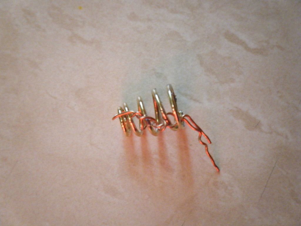
If you mean how to use copper braid, it has to be soldered at both ends of the spring, usually run through the center of the spring, with just a little slack. Depending on soldering skills and the plating of the spring, you may need to sand both ends of the spring, to get the solder to stick. Too much heat will cause the spring to loose… it’s spring and the spring will be useless. If you have a spring on both the + of the driver and the tailcap, I would suggest using a small piece copper round stock instead of the driver spring and do the copper braid mod on the tailcap spring. Copper braid can be bought in Radio shack, in the US.
When we measure current , and say there is a spring in the head , if we dont compress the spring all the way ....
What happens ?
The current has to travel further along the wound coil , more distance = greater resistance
When you press hard and crush fit or compress to the max , you shorten the distance the current has to travel , this = less resistance ..
Also when you crush you also increase the size of the path [ like increasing wire size ] this also aids current flow ...
When there is no spring , and you press hard , you may be increasing the surface area of the contact , = less resistance , larger path for current = more current .
If you wanted to you could solder some wire to the top of a spring [ closest to batt ] and then to the switch or driver , increasing path size - lowering resistance - and possibly shortening said path ...
Surely cant hurt as long as you dont introduce a short circuit ...
This is a commonly used trick in DIY/mods. Be careful with braiding as it can screw up the emitters in DD lights.
Lambda lights specifically asks users not to braid/solder up them springs. Over current. The ultra small resistance in the spring(s) and wires are the "drivers" / current limiters.
I would guess the biggest factor is the actual connection point to the cell, rather than the gauge or length. Those little copper caps on some springs, would be good to get hold of some and try measurements with/without.
Yeah many of my lights are direct drive, increasing current may only increase lumens for a brief time until warming occurs. So the added resistance may not be a bad thing.
I have had what is just about an opposite experience. I have several lights that, if I tighten down the tailpiece all the way (maximum spring compression), the light either shuts off or blinks/disconnects. Once I loosen the tailcap a turn, everything works beautifully. Perhaps a bad solder point in the pill?
On a separate note, while we are used to thinking of amperage in the 1-4A range, 4 being HUGE, in reality the diameter of the spring is pretty large. and it is solid copper. I would think it would be able to handle a 5A draw just fine, without any supplemental ground. So call me cynical, but I think something else is at play here.
I also measured the diameter of the cheapest host I could find (502b) and found it to be .03", which is the equivalent of 20-gauge wiring. 20 gauge can handle 7.5A at 12v, so I don't think the resistance of the spring would play a big part in how many amps are getting to the pill.
I tried putting more/less pressure on the battery (compressing the pill's spring) on about 6 different lights. I could not get a variation of more than .1A on any of them.
 and the spring will be useless. If you have a spring on both the + of the driver and the tailcap, I would suggest using a small piece copper round stock instead of the driver spring and do the copper braid mod on the tailcap spring. Copper braid can be bought in Radio shack, in the US.