moved offtime cap to top of board (so PB2 is automatically available on top now)
Obviously several traces and vias moved to facilitate the changes. Everything passes DRC (other than all the intentional overlaps & stuff). Minimum trace width on the board is now 13mil (between the ATtiny13A pins), DR allow for a minimum of 6mil.
One is that I finally got my brain-cells lined up and did the freq calculation. There are three main factors we control which affect the frequency (remember we are capped at 2Mhz):
inductor L (inductance in units Henry)
input voltage minus output voltage (a wider gap means higher freq)
output voltage (higher means higher freq)
Clearly when building a driver one must consider the #2 and #3 factors when choosing what to use for the inductor (#1).
From what I can see, the absolute minimum inductor we could use while driving a single XM-L (call it 3.4v) from an 18v source would be ~1.414uH. Working in the other direction, I find that if we use a 3.3uH inductor that puts us at about 856kHz with the same XM-L and 18v power source.
Driving an MT-G2 at 8A it seems to me that a 3.3uH inductor will give us a frequency of about 545kHz.
Two is that as far as I can tell, with some help over here, there are perfectly good Schottky diodes in the 8-15A range in a package called POWERDI5 which will fit on this PCB just fine. I borrowed an Eagle package from Robert Starr and added some legs to it to better represent what we’re actually laying down on the board. I think everything fits quite nicely. (At 5A many packages are available, there’s plenty of space here for any with this general shape.)
POWERDI5 has a large heatsink tab on the bottom, but I don’t think it needs the huge landing pad specified in the datasheets.
Cut down the end of the POWERDI5 landing pad to allow moving the diode closer to the edge of the PCB. (this improves space for large SMD inductors: we should now be able to fit 8x8mm inductors again)
Maintained 0805 footprint for the QX5241’s Vin smoothing cap (the one right next to the QX5241 on the bottom) but cleared enough space around the pads to allow a 1206 cap to be installed. This keeps costs down for the 47uF cap specified some of the datasheets for this chip.
Power trace for Vin moved to facilitate the 1206 cap and keep it away the BAT+ spring. The previous placement had issues after I installed the big diode. (it would interfere with the diode’s heatsink pad on top or the BAT+ spring on bottom)
Cleaned up voltage divider area to allow symmetrical vias again.
You went right over my head(my brain operates ~1hz, or 1 idea/day) but the trace lines are looking much cleaner and pad spacing is better for soldering.
The design feels like it’s stabilizing, and I see the usefulness of the original all-transplant board still. So I made a b-version with a TO252 and external inductor again:
I enjoy following all the circuit design threads that have been popping up as of late. I love the initiative here on BLF
I’m an ME student so the little education I have re: electronics/digital devices is basic so forgive me if this doesn’t help :). Since you want to maximize heat transfer paths for components incurring high I^2*R losses you may desire a layout that subsumes and utilizes the space occupied by the SMD inductor pad. I had to research passive elements for one the technical reports I did in Circuits II: System Dynamics. Here’s a short excerpt from the section dedicated to general advantages of the toroid over cylindrical coils (please excuse MS Paint fudgery - the flux lines would go the other way):
If you can figure out a layout that places a toroidal inductor nearby the components with the lowest profiles, you’d make more room for heat paths - maybe even without significantly impacting host compatibility. A (non-metallic core, usually ceramic - e.g. ferrite) toroid’s high specific inductance lets it be smaller than an equivalent value SMD inductor and will increase quality factor (lower heat loss).
Thanks for the input Slim Pickens! I need all the help I can get, I know very little about most of the parts involved here. The SMD inductors in question are very small, <8x8x3mm or maybe 6x6x4mm. I haven’t really seen much in the way of wire wound toroidal inductors that small. I’m having trouble with finding a place to purchase toroidal inductors of any size which specify RMS or Saturation currents, much less little bitty ones. Any suggestions?
It’s a getting late for me right now to figure out how to calculate inductance from turns and the like for a given toroid bead (need to get up early). But, tomorrow I’ll be more than happy to try to help out.
There are a couple of promising cores from Magnetics Inc. Their XFlux and High Flux lines are of interest for our application. Their product pages at least shows how to interpret Magnetic’s product codes. I’ll look into it tomorrow and let you know
Cool, thanks again and in advance. I suppose wrapping our own toroids would add yet another aspect to our hobby.
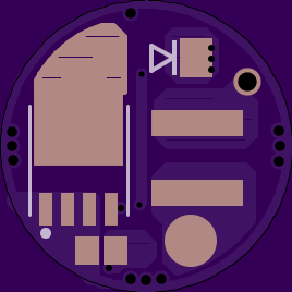
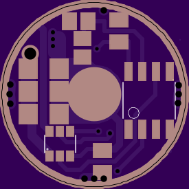
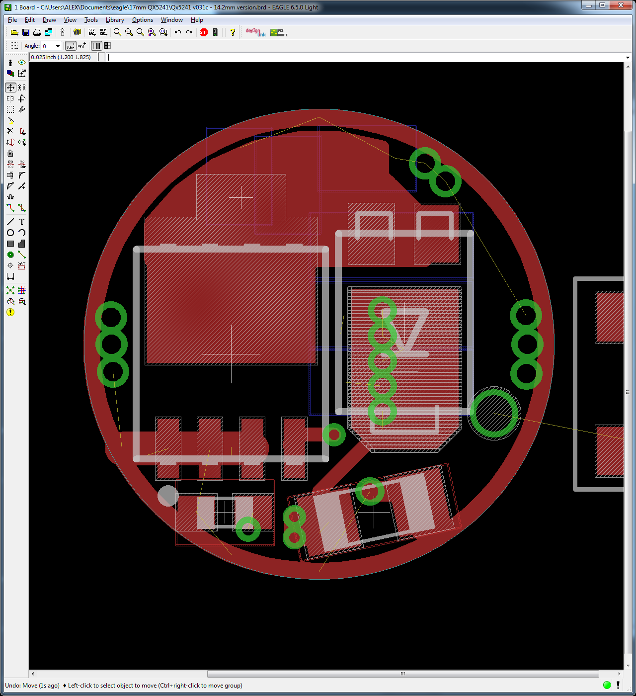
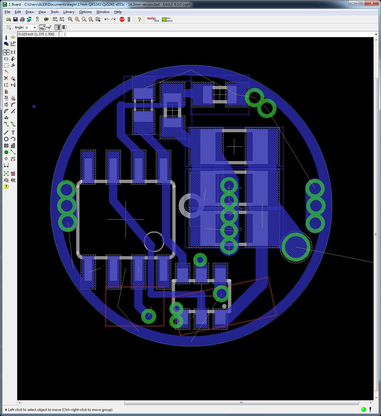
In the meantime I decided when I went to bed last night that I could make a 15mm version of this driver. Here’s the 14.2mm version. J) It’s got a 0.5mm component keepout all the way around just like the 17mm version, but the inductor must sit on top. There’s still a big 1.1mm via to wire the inductor to. You should be able to use the small SMD inductors with a short air wire coming up from the via (maybe later with Slim Pickens’ help we can switch to an even smaller toroid). If you need battery contact on the driver you’d just make a mound of solder/copper/whatever on top of the sense resistors in the middle - I marked the center with a little circle. I’d build this driver in the opposite direction from the 17mm version: first the top, then the bottom. That way you can tell if there’s a problem with solder making it’s way through all those vias under the 1206 sense resistors. I switched the (possibly) 47uF input filter cap for the QX5241 up to a 1206 and I switched all the other 0805’s down to 0603 size.
This should make it pretty easy to build a high-powered 2xAA mini-mag?
Looks like a 1/2 dozen beads under 8mm OD and 4 mm high but that’s without windings. The one pictured above has 60 turns (guesstimated) 8-10 mm wire /turn > 480-600 mm wire (call it .5m). 60 turns of 24 awg at .5 mm dia would require a toroid bigger than the driver. Resistance would be.04 ohms which seems high(40 mohms at 5A is .2V drop). A 7 mm toroid with an ID of 2.16 mm could only fit maybe 6 turns of #24 so maybe the small size required precludes too many turns. I know the guys building joule thief circuits play with these puppies so maybe they might have some input.
You have to be very careful specifying and using inductors. Put too much current through them and the core saturates, they stop behaving rationally, and that tends to let the magic smoke out of circuitry.
I’m taking care about the saturation current from the datasheets, and keeping an eye on RMS current as well. I’m also trying to ensure that we use the highest inductance possible with compatible Isat / Irms values - this is in order to keep freq down to minimize switching losses. I’m ignoring core materials because I know squat about that, but I glance at the graphs when available to make sure whatever materials are being used don’t cause anything too crazy.
Beyond that is there anything else I should be watching?
EDIT:
I think that I have not specified any inductors in this thread. I’ve gone through several, but here’s what I think I was looking at most recently: MPLCH0740L2R2 ASPI-0630LR-3R3M-T15
I did some reading and hand calculations. I came up with three potential choices of toroid beads. I’ve only looked at what Magnetics Inc. offers but I can tentatively say that the results actually don’t sound too bad.
They’re all roughly 5mm thick unwound - one bead is actually 4.6mm thick before winding.
Each option requires 7 turns or less of wire. Wire size TBD.
I’ll post what I found this evening including scans of the hand calculations, complete with stream of consciousness ramblings in the margins.
I’m mainly looking into powder cores because they at least offer soft saturation and don’t suffer quite the sudden ‘critical existence’ problem as a regular ferrite core. Just in case.
Thanks, I’m looking forward to seeing your findings. If we can get big current out of the toroids, or even big efficiency, it will be worthwhile in some lights. I’m glad I managed to keep a big via to accommodate an external toroid. That said, it won’t work in P60’s or other small lights - we’ll have to stick with the SMD inductors in those applications I think.
Using the design suggestions on Magnetics Inc.’s website I came up with 3 beads for different uses. Selected to operate fine at 18V input. The one thing I didn’t figure out was calculating core losses, which increase with frequency. Despite that I was otherwise pretty conservative when I spec’d these.
For high currents (up to and a little over 7A) with an MT-G2, their 0055047AY bead :
OD (max) x ID (min) x h (max) = 13.4 x 7.16 x 5.34 mm
7 turns
For moderate currents up to and a little over 4A, their 0055265AY bead :
7.06 x 2.33 x 5.24 mm
5 turns
For moderate currents up to and a little over 4A in hosts where driver height is more of a concern, their 58128A2 bead (direct link to PDF) :
11.9 x 5.84 x 4.6 mm
7 turns
_
From my understanding a lower switching frequency and higher inductance (more turns) would be feasibly reduce ripple current —> higher permissible drive current for a given core and possibly lower core losses provided saturation is avoided. It seems that is where a toroid would shine given their intrinsically high Q factor and inductance.
This design document from DigiKey and this article were really helpful. So was this one from TI that compares asynchronous and synchronous buck converter topologies and their relative strength and weaknesses. All that was a bit to take in, but really interesting.
Looking forward to seeing this driver come to fruition. A 3+ A MT-G2 2x14500 Mini MagLED would be awesome. As would a regulated 4+ A XM-L2 in a 2x18350 Convoy M1, or to an XP-G2 in a C8 using 2x18350. Subbed.
June 24th Edit:
Links to parts fixed!
Edit 2: Tried editing the links to design documents. They appear to work now.
OK, so… I figured out how things got hooked up wrong in the schematic. I’d done my pin definitions on the DPAK/TO220 EDIT: DPAK/TO252 part wrong! So I just eyeballed connections on the early revisions of this board until they were correct (the FET is connected correctly until I switch to LFPAK, but only because both the part and the schematic are wrong…).
So later when I corrected the schematic to get my properly built LFPAK56 part hooked up, that was OK. But then I was 100% blind when I posted v30b in post #44… I just swapped the part back to DPAK, but with the incorrect pin defs on the part I was using it turned out a mess. v30b is no good.
So now I’ve fixed my TO220/DPAK EDIT: TO252/DPAK part.
EDIT: clearly getting those pins mixed up was not the only time I’ve gotten mixed up
Good news: not the show stopping kind I think. I’ve screwed up somewhere. I received a set of v029 boards from Oshpark. v029 only has minor tweaks to trace width or placement versus v028 from post #42.
I stripped the components off of a 2-amp DX sku20330 board and then assembled them on my v029 board. I don’t think I tested the board before I stripped it.
I did not add an MCU or MCU support components, only what came off of the DX board. I strapped VCC (LDO) to DIM, which is the PWM input. This is the recommended setup for using the QX5241 without a PWM signal, but I did also test with DIM floating - this produced the same results. Pulling DIM low does shut down the output, as it should. I did install the cap for the the LDO output as well as the input cap. The only component not used was a 000 jumper.
Output is not regulated!
The minimum input voltage to light up the LED is about right (~4.5v or so)
at 4.5v it’s not pulling enough current (<700mA)
at 16v it pulls too much current (>1000mA IIRC)
voltage across the sense resistors seems too low (0.08v)
I tested another sku20330 board and it did not behave that way, it behaved as expected (input current much higher at low voltages and much lower at high voltages). I can’t think of what I’ve done wrong, so I suspect that I’ll have to take this driver apart and put the stuff back on the original PCB to be certain that the components are OK.