[QUOTE=DEL] driver we are at 81-85% of true direct-drive numbers. The modification takes it to 91-94%. None of this will be very obvious in real use. So stop sweating the numbers and enjoy the light :).
[/quote]
I knew this was the case, at least with my lights. It’s not a huge deal. I just knew it could do better. I will try the mods suggested and see what it does for mine.
I’m really liking this light! Dale, I’m sorry I didn’t convey the joy I had when I first held the light. There was a very nice smile on my face. And still is :bigsmile: thanks for your work! And to all the others as well!
So, if there is no LVP on the driver and I only use my light in turbo would it make sense for me just to bypass the driver on this light? What would be the best way to do that without ruining it in case I’d like to go back to using modes in the future? I do have two more lights on the way so I wouldn’t mind tinkering with one.
Make the black driver lead touch ground, then it will be full time direct drive. The tail switch will still turn it on/off you will just be bypassing the control of the MCU.
At the emitter, a wire soldered over to the body will do, easily removed later. Or even a wire soldered onto the mcpcb and left bare for the reflector to press onto, this would make it direct drive with no modes. Switch would still work.
Likewise, soldering a short wire onto the base of the black lead, on the driver, and letting it go to the ground ring, direct drive, switch turns it on/off.
Vjik, that looks awful! My light is flawless, there wasn’t even any dust on the reflector.
I still can’t believe how much I like this light. I’m so disappointed that a lot of the other lucky sun/ nice nature/ Palight’s are out of stock on Gearbest because I’d like to buy some more.
My 219Cs run just fine; I’m not running any critical over-amperage. However, the stock reflector of the D80 is not optimal for the 219C LED’s dome emission unless it (the reflector) is modified. I took the easy way out and performed a reflector-bypass on the D80.
I designed a 2-spacer ring unit from black ABS plastic.
MEM, did you glue down the mcpcb? It looks high on the left side in that picture, like it might be floating. Otherwise, what’s holding the mcpcb to the shelf with the aspheric lens in place and the reflector removed? Or are you running the aspheric above the reflector? Focal point? Adjustability? The enquiring mind wants to KNOW! lol
Looks sweet anyway, that D80 style with the fish-eye glass….
I have the Nichia 219C in a bare aluminum A6 with that lights FET+1 driver. If I put a top cell in it, the emitter pulls too much current and turns blue. Using a Panasonic PF cell it pulls about 7A and is ok with that. 11+A is more than it can handle. So the FET driver will give all it will pull, if there’s enough cell, it will pull itself into oblivion.
Edit: Keeping in mind that this one has a 1.8A max rating, and is a Nichia not a Cree, it’s really doing a sensational job. Nichia used to be known for not having tolerance to overclocking, this 219C is a step up for this class. The higher CRI (80) makes less lumens output but since they haven’t decided to make a higher CRI than that (the promoted 93 CRI) I guess we either go with 80 or a non rated high output variant.
I took that 219C picture of the BEFORE setting the D80 up for my “assembly” for the aspheric lens. (Also, the PCB is actually not high in that pic, the grease I use really sticks down after thermal cycling in an arbor press. It could be run that way, in my scenario, as it would take leverage with a screwdriver to get the PCB to pop off the surface.) I have the aspheric internals removed in that picture and just the reflector spacer is on. The aspheric setup looks completely different. Two, flat-button head torx screws get drilled and tapped to hold-down a large spacer plate for the reflective collar spacing and alignment that also pin down the PCB.
With one of the top cells, I’m only running 4.7-5.0A with 219Cs. But I will be using de-domed XP-G2 S4s as well as V3 XPL HIs—but the 219Cs look good with the domes on!! —That is something I never thought I would say about any LED behind an asphere. I made a small exception with Nichia. 0:)
I have newly designed, visible-spectrum AR-coated aspheric lenses being ground right now, which have a slightly larger NA than the lens in it, and have about ~12-15% more throughput than the lens in it. The lens front will clear the bezel for the aspheric configuration. So it should head-stand just fine. Then I have caps which pop-on the D80 that are disposable/replaceable, to protect the aspheric lens from the sometimes odd places they find themselves in. There will be no damage to the important parts today, so long as the D80 is wearing protection.
I was originally only building about 15 aspheric D80s total, but it looks like I’ll have around 30 total aspheric D80s, so after the spoken for units there is actually about 20 aspheric D80s which remain. Earlier I had said only 9 remained, so that number about doubled, at this point, due to a larger order of lenses to bring the price down.
Nichia really sunk the die down into the package on this one, and used a strong semi-conductor region, strong as in “it takes amps and keeps on ticking”. The reason for their lack of ability to 100% successfully de-dome in a solution is due to this fact combined with the heavy phosphor layer they use. It is like MTG2 phosphor, but better as far as light passing through it—though not as strong as thin Cree phosphors due to this. It’s like Nichia grew a less-dense, fluffy, but thick phosphor to pass light, and as such, it will not pull away from the dome very easily without flaking.
It’s like an ELF that we pretend is a BLF to confuse ourselves to say it’s all cheap, but I ask; who is quantifying the B on this LF? I certainly do not agree with them. :bigsmile:
Some quite irrelevant stuff I'm reporting here, it is all about a few percent. But we're BLF and freaks so this is what we do and want to know :-)
I did the recommended resistor-stack with 150Ohm on my 5A D80, easy enough mod :-)
Measured light output before/after, same 30Q at 4.07V, measured after 10sec (so nothing standardised, but exactly the same way before and after the mod). Before: 1040 lumen, after 1100 lumen. One of the easiest 5.5% gain ever and I understand that the gain gets better when the battery drains, thanks for finding out sharpie/DEL!
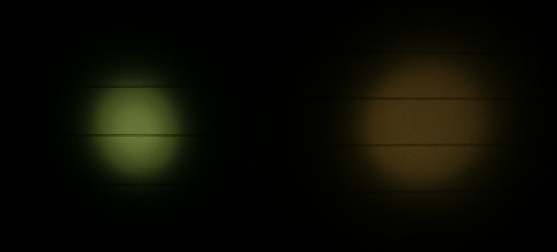
One thing someone else noticed before, the led is not always on at highest setting (also not when the 150 Ohm resistor mod was done). I tried to catch that. First an underexposed (to get the 'shutter speed' high) picture of my two D80's hotspots, dedomed 1A on the left (yes, I have to get the focus better) and the 5A one on the right (after the resistor mod):
No, it is not my camera, I checked, another light does not show this with the same setting. and the black stripes on the left hotspot are not on the same height in the picture as the ones on the right spot. So the light is off 5% of the time. So that is another possible 5% they missed, and another reason why bypassing the driver gives higher output numbers.
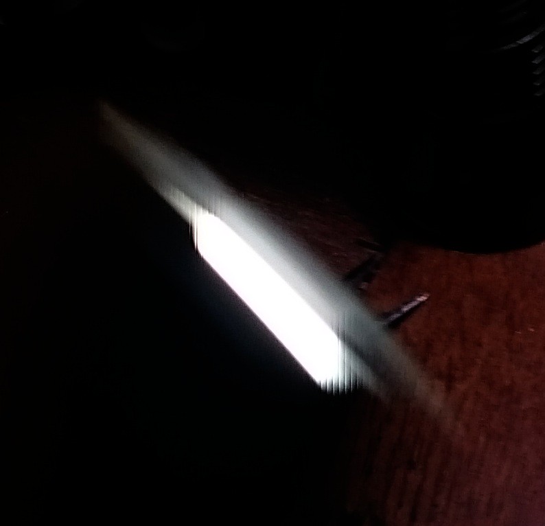
another way of showing the same, a waving picture:
I have done this often enough to know that this is high frequency, in the order of 10kHz.
Same problem with the lights i received. the tail retaining ring just fell out everytime i screw in with a battery. Also i tried using a Eagletac 18650 protected and it is not working. So i try with a AW 18650 protected battery and it works.
Should i mod a shorter tail cap spring or buy a longer body ….hmmmm……seems like it is expected for a budgetlights.
Yes, this driver does have PWM on all modes.
As per an earlier post, on ‘DD’ mode I measured around 0.080 ms off every 5.405 ms (185 Hz PWM) on an oscilloscope, or 98.5% on.
I did not see something around 10 kHz, but I was not looking for it either. I can dig up the driver from the parts bin and re-check it if you are interested. My second D80 should be in this week as well.
For people doing the gate resistor mod, I would recommend your method with a 100 to 200 ohm resistor. With a straight jumper there is significant ringing every time the FET switches on. Does not seem to affect operation, but bad in principle and may affect longevity of the FET or MCU.
And, as sharpie mentioned, the stock design does not make sense and it is surprising how well the driver is doing without this mod.