I proved the fuse thing already . Fortunately I got spare springs and no apparent harm done - to the light or cells. I had only 2 GA cells in at the time, one upside down - noticed no light blink or flash, then saw a nice little stream of smoke.... The springs turned blueish and collapsed - usual thing. I've seen this before.
I'd like to see I took one for the team and tried it, but...
I now use the temp control and set it to a new tem. Worked like a charm! Thanks Tom and Lexel!!! But i have another question. I checked the datasheet from the VTC-6 and they can be discarged way below the 3,0V. Is there an option to set also the LVP levels?
Well, only in the code - there's a setting for that, but in reality, how many mAh are you gaining? If you look at it, not much is left below 3.0V. Some wanted to use a higher cutoff even.
The VTC-6 are going down to 2,0V. I do not know how many mAh i would gain if the cutoff is set to 2,5V but i have a heavy modded TN-31 and the cutoff there is set to 3,2V/cell. If i use the cells than in a light without LVP i got quite some extra runtime untill the cells are below 2,5V. So it would have been nice to be able to get this extra runtime by setting this cutoff via the modes. But so i have to wait for the next bigger mod (when i have the time to flash the mcu with changed values.
I will definitely ask you again how to when the time comes. So far i am really happy. And i am impressed how long it took to get to 60°C headtemp ~22A on turbo. That speakes for the design!
With the Luxeon V this time will be much shorter (@~35A :smiling_imp: )
’Twas discussed, ad nauseam, fusible traces, SMD fuses, etc, but too complicated to introduce into this design, from scratch. Complexity and cost, for something that hopefully may never happen to most. And bearing in mind selling price. Fusible springs (intentional or otherwise) will probably do the job well enough. If you beef them up, you take the responsibility to operate the torch safely.
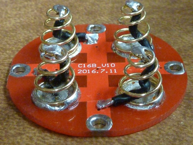
Has anyone considered that the resistance of the springs comes from the gaps, that if the springs were compressed more OR the gap filled, there would be no gain from bypassing.
How about simply feeding braid onto the spiral of the springs so that when compressed there is a crushed braid under the battery, no need even to solder? Viable?
I don’t understand and can’t tell from the picture what you mean. Did you drill and tap holes in the battery tube?
VWPieces:
I’m hoping someone will sell off kits with quality right screws to me, actually. As I don’t know for sure what I’d buy by the hundred.
Too much of anything becomes a burden for one’s survivors, after enough decades of accumulating stuff. My estate sale will make hardware junkies happy.
I can't follow the copper braid mod either - don't understand where the screws are. My method is not dependent on the screw as well. Literally about 1 mm, maybe, is used on the PCB. The ring around the screw hole is soldered so it sits above the solder mask, making contact to the bare aluminum of the battery tube.

 . Fortunately I got spare springs and no apparent harm done - to the light or cells. I had only 2 GA cells in at the time, one upside down - noticed no light blink or flash, then saw a nice little stream of smoke.... The springs turned blueish and collapsed - usual thing. I've seen this before.