My new DROK USB meter says 8.8mOhms on one and 9.2mOhms in conjunction with a Cottonpickers charger that has very short 20ga leads.
Thanks for that Pete, but that kind of testing is not for me. I’m too forgetful, too easy to make a mistake. And I’m not about to be the guy that direct shorts a 30T!
1. Solder one end of 30cm 18AWG wire to 2x brass buttons for nice contacts.
2. Solder the other end to the legs of a 5 Ohm resistor.
3. Wire a switch through the wires.
4. Clamp the brass buttons to the cell with the switch off.
5. Put your multimeter on voltage reading mode.
6. Measure the open circuit voltage of the cell. For example, it will be 4.2V.
7. Flip the switch, and measure the voltage of the cell instantly, then flip the switch again. The noted voltage will be 3,9V
8. Do math:
ΔV = voltage delta = 0,3V
R = 5r = resistance used
V = cell voltage = 4,2V
VL= Voltage under load = 3,9V
C= current flowing
V-VL = ΔV= 4,2V-3,9V = 0,3V
C= VL/R = 3,9V/5t = 0,78A
Internal resistance = ΔV/C = 0,3V/0,78A = 0,38R = 380 milliohm
Yeah, that is the real internal resistance of a cell, and how you calculate it.
1. Why such long wires?
2. HKJ used a 10 Ohm
3. As if a flashlight modder that looks for maximum brightness is going to have a whopping 5 or 10 ohm LEGGED sense resistor! SMD, in very low ratings, that’s what I have. Perhaps I could identify one on a board from a piece of broken electrical equipment…
4. NO metal clamp! ![]()
5. So you’re saying to use the probes of the Multimeter to measure the Voltage, with the 30Cm 18ga wire attached and switch in off position. So there’s just the one 18ga wire attached with a resistor inline as well as a switch inline, won’t the switch alter the resistors value, or won’t the 11+” long 18ga wire do the same?
If I do this and y’all never see me post again, you know I went up in flames…BLUE flames probably. ![]()
An experientially valid method for testing actual DC IR is to prepare a setup with multimeter leads directly attached to the cell terminals (mV precision or better preferred), and apply a sufficiently high current to measure at least a decent variation in no load versus load cell terminal voltage. Current needs to be applied without meddling with the multimeter leads. I've done this with a precision power supply, 2 pieces of copper sheet and a couple neodymium magnet stacks to held them in place at the battery terminals, and a friend to lend a hand:
- Measure no load initial cell voltage. Note it down.
- Apply current, 5A for example, for a given time lapse, let's say 10 seconds.
- Note down cell voltage exactly at half time (t = 5s).
- After stopping current flow at t = 10s, wait a few seconds more for cell voltage to more or less fully rest, then note down final cell voltage.
- Cell DC IR is then RcellDC = V / I = (Vload - (VnoloadEND + VnoloadSTART) / 2) / I
Cheers :-)
The lower the resistance, the more current will flow from the cell, so it just depends on what working conditions you want to simulate during the test. A 10 Ohm resistor will result in about 0.4A current flow. A 5 Ohm resistor - about 0.8A.
0.8A at 4V gives you 3.2 Watts of power, so you have to make sure your resistor can handle it without overheating and burning out.
So getting back on track we now have a host version, which i ordered two of. However, it doesn’t specify what size driver or any details about the mcpcb it comes with.
It’s probably the same MCPCB size.
However, I know nothing about the driver.
The host typically ships WITH their triple copper MCPCB and the triple reflector. All you need is XP footprint emitters and the driver. The size of the driver, I’m not sure of. Just ordered the host myself so I guess I’ll find out in 6 months when Teacher’s slow boat goes back to China to get mine and brings it back over…
The retaining rings are now aluminum. Probably cost-cutting. I like ’em brass on both ends.
Is there a reason you don’t like it?
I don’t really know why. Aluminium and brass are both easy to machine, aluminium has higher conductivity than brass, etc.
Am I missing something?
The whole flashlight is aluminum. So why care that tiny bit?
Convoy C8s all have aluminum driver retaining rings.
I’m more used to the older C8F and their earlier lights like the SF36 and SP31s. They use thick retaining rings that look like brass. It has better structural strength than aluminum, IMHO.
Hey, we have our own preferences. To each his own. Just because Convoy uses aluminum doesn’t mean every manufacturer should follow suit.
I understand you just I don’t bother with this. :+1:
I don’t like Aluminum retaining rings either, they tend to strip out and are always loose causing poor ground contact.
If a brass ring strips you can solder it to the driver’s ground ring. Not much you can do with a loose Al retaining ring. Toss it, head for the lathe…
Re: Aluminum vs Brass retaining ring for tailcap switch -
An OVEREADY article on the retaining ring topic noted that most tailcap designs of this type have the end of the aluminum battery tube butting up against the retaining ring. Since aluminum butting up against aluminum tends to cause more friction and binding, this can result in unintentional unscrewing of the retaining ring when unscrewing the tailcap. Brass, on the other hand, is a low friction metal and reduces binding and accidental unscrewing of the retaining ring.
This site has brass and copper retaining rings but for standard 18650-sized tailcaps:
http://edcplus.com/accessories-mcclicky-c-3_29.html
Will it fit the C8F-21700 tailcap? dunno.
If we buy an empty host (without the driver board):
Where would we find a driver with the side button setup where the side button on the board matches up at the correct location with the host? Do most driver boards with side buttons have a standard location?
You might be confusing Sofirn with Lumintop. Lumintop has a lot of current lights with the switch built onto the driver. This Sofirn C8F has a separate switch and driver so it’s relatively easy to change the driver. You just need to solder the wires from the switch to the driver. Make sense?
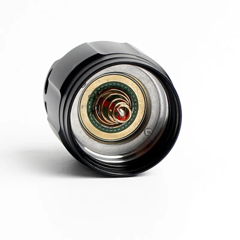
Here is the 18650 version switch.

.
Does anyone know what size driver this light uses and if there will be enough depth to clear an inductor on a boost driver?