That is some great news :bigsmile: thanks for the update
As i said i would love to upgrade my triple X6 with the BLF17DD to one of your creations, i really can’t even imagine anything more that could possibly top that
I can’t wait for the testing to start i like to wait for something good to come
I got the 10mm FET+1 built and in the Texas Poker this evening. :bigsmile: Reversing with the A6 firmware, hidden loop for the Strobe and battery check, this little light is in hog heaven!
While I was at it, I put a new XP-L V6 2C in it. While I do love the 3D tint, I find the warmer tint not as much to my liking in this particular light. So now it’s got the ultimate driver, the ultimate firmware, the ultimate (mostly) emitter and the ultimate cell. Oh Yeah Baby! lol
I’ve got an Efest IMR in the charger, just got finished with the build a few minutes ago. Ate a cold supper trying to finish it. lol Should have an amperage and lumens/lux set within the hour.
With my newest Efest IMR10440 charged at 4.20V it just hit 1045.35 lumens. :bigsmile: Of course, that’s a start number and the little cell falls fast right out of the gate.
Good job, it looks like these LFPAK33 can push the amps a little higher
I have been enjoying charging my Efest 10440 to 4.25v for a surprisingly big boost of output the first 30 seconds
I mostly use the 4.25v trick, when i want to see the max a new build can do, but these little 10440’s really gets a lot stronger at 4.25v and i mostly recharge them before 3.8v anyway
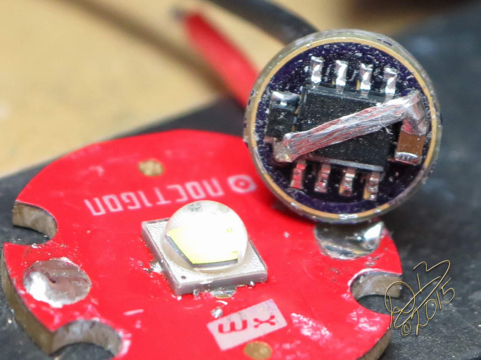
If you use an attiny13a-mmu a 10mm can be made to fit single-sided, with all of the normal parts and an LFPAK33 FET to boot. Dang thing pulls the same amps as a big 17mm FET driver, along with full firmware compatibility. Will be sharing the Oshpark project after more testing is done, but it has run for several hours on the bench now so I feel confident in it, just needs some time in an actual light now first (I generally don't release things until they have been tested). Probably later this week.
Tiny, isn't it? You don't get the full perspective of the size until you see it next to something else!
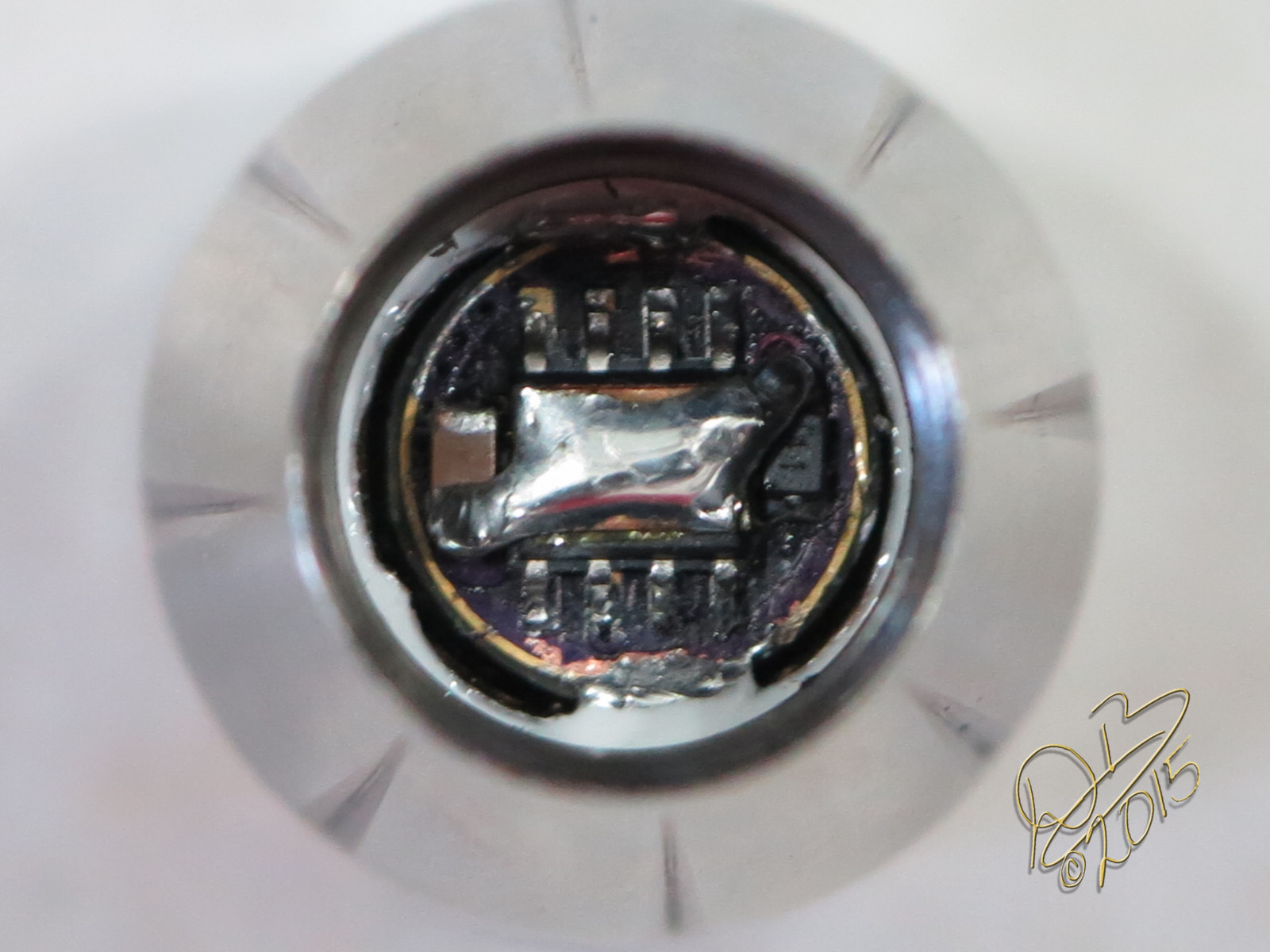
I sanded the outside of this one a little too far I think. After actually measuring two different 10440 light's drivers, it seems that most of them are really 10.5mm/11mm. I think I'll make them 11mm in the future but with a ground ring that can be sanded to fit.
This one isn't quite as cool though because it doesn't have a 7135 as well. Maybe an "air wired" 7135 should be the way to go?
The board is already there on Oshpark for you to DIY if you'd like, but if I keep on building drivers with the MMU then yes I will also offer them pre-flashed. The MMU is a bigger pain to flash and reflow and is slightly more expensive, so I'm only planning on using it where it can provide a real advantage (like on a 10mm board!).
I have been imagined this driver, ever since i got it in to my head that i wanted to put a FET driver in my Olight i3s.
I hoped that with the MMU it could fit for a single sided 10mm fet driver, and i am very pleased that it did, thanks for proving that i have been wondering about it for months now.
How big smd components did you use?
You mentioned the 7135 is there enough room for pads for air wiring it? If it is you can always add it on later (the 7135 i mean) if one can fit the extra hight, if there is pads for it.
I can’t stop looking at it is so tiny you could drop in & fit that to bypass the driver in almost any light
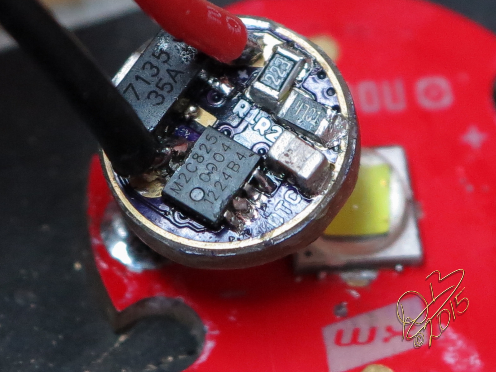
I took the tinned strands of wire off that bridged the MCU between the cap and diode and stuck a properly sized piece of Kapton tape on top of the MCU, then soldered in a rectangle of copper for the battery contact. This tends to be more stable as it doesn’t move at all. It also allows me some adjustment of stack height by controlling the solder on top of the copper.
Also polished the OP reflector, something I’ve been meaning to do for a long time
The XP-L V6 2C in the newly polished reflector…
Moon mode…
That circle of light is actually smaller than our standard 17mm drivers, yet still puts out 1000 lumens, crazy!
Rich, the mmu looks like it can bridge the gap between the 13A and the smaller pic chip. Does it have the same memory as the larger package? Also, does this new board have a B+ via big enough for the led+ wire to pass through the board instead of the solder bridge over the 13A? Normally, several small vias would carry more current than a single larger one but the larger via allows for a spring bypass direct to the star.
Awesome job Dale, I’m surprised you even had room for a solder blob. I know Alex said the mcu pins could take the strain of thread forced pressure but I still think some form of package support for the Attiny advise able since for the first version of this driver he had a hoop in mind. I tried two different ways, the first was to just JB the 13A in place and allow that to cure before soldering and the second was to squeegee some JB between the pins after the fact. Either method seems to work well enough. How did you avoid scratching the reflector?
The MMU is functionally identical to the regular size 13a. That's the whole point. Exact same programs and functionality.
There is a pretty big pad in the middle for the LED+ wire. It is a personal preference, but I dislike soldering wires into vias. The battery side is completely smooth and I imagine that most will run this without any sort of spring in place.
And 400 grit and 800 grit and Mother’s Polish. The real issue was the same I’ve seen before, they turned it mechanically so there were imperfections in several places creating lines perpendicular to the light path. So I sanded it top to bottom, in and out, tiny as it is that was quite difficult to do. I used a pencil eraser to push the strip of wet/dry sandpaper while holding under a stream of running water. Then polished it in a circular motion again, cross grain to the sanding. Got out virtually all the rings, but I see in the pics that I left a couple of sanding scratches. Oh well.
Ah, there are still legs of wire under the ends of the copper pad. And I flattened the legs of the MCU before putting it on the driver. Placed it on the table and squished it. So it sits flat on the board, lol. Good bad or ugly, that’s the way I did it.