Hi cherkess_jan,
You find the formula explained in the STAR firmware of member JohnnyC:
VOLTAGE
Resistor values for voltage divider (reference BLF-VLD README for more info).<p>Reference voltage can be anywhere from 1.0 to 1.2, so this cannot be all that accurate<p>VCC
  |<p>Vd (~.25 v drop from protection diode)
  |<p>1912 (R1 19,100 ohms)
  |
  |---- PB2 from MCU
  |<p>4701 (R2 4,700 ohms)
  |<p>GND

ADC = ((V_bat - V_diode) * R2   * 255) / ((R1    + R2  ) * V_ref)<p>125 = ((3.0   - .25    ) * 4700 * 255) / ((19100 + 4700) * 1.1  )<p>To find out what value to use, plug in the target voltage (V) to this equation
R1 and R2 are a voltage divider, the voltage that is measured by Pin7 of the Attiny13a has to be brought below the reference voltage of this MCU which is 1.1V. Values below 1.1V result in a value between 0 and 255 which can be translated to a certain voltage at Pin7 and its equivalent, the cell voltage.
This is used to recognize when the voltage is below a level critical to the cell (to get low-voltage protection) or to measure and blink-out the cell voltage in general. In your case, planing with a fixed voltage power supply, I can’t see the need for measuring the voltage. But if you want to do so, you will need a divider that brings 12V down to 1.1V, so R1 should be roughly 10-12x the value of R2.
Sorry if some comes double with what TomE already wrote, but I had written the answer before I read his and now I just copy-paste :innocent:
I might have said it before, I haven’t heard of someone using this driver with 12V, it’s designed for single cell (1S, 4.2V) and prepared for 2 cells in series (2S, 8.4V), which already gives problems with the 7135s. I wouldn’t bet that 12V will work, perhaps as a FET-only driver. But if you get it working, be sure to let us know. :laughing:
.
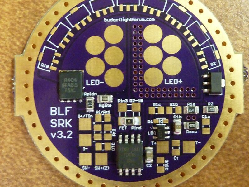
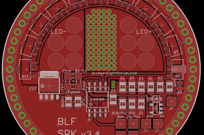
And here’s a teaser for TomE.
Yes, those are 70 LED+ vias and they don’t have soldermask. 
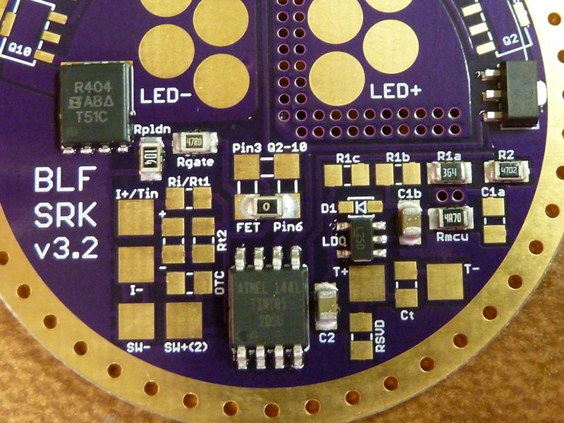
And some more optimizations for high current, might that be of any use?
I just have to double-check the oshpark preview and finish the doku.
And the tabs, of course.
.
.
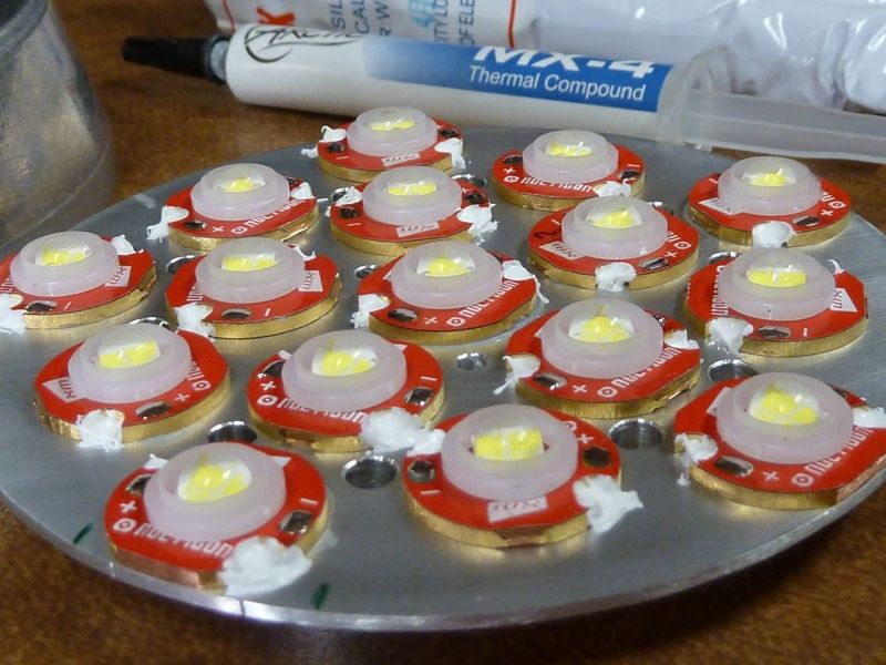
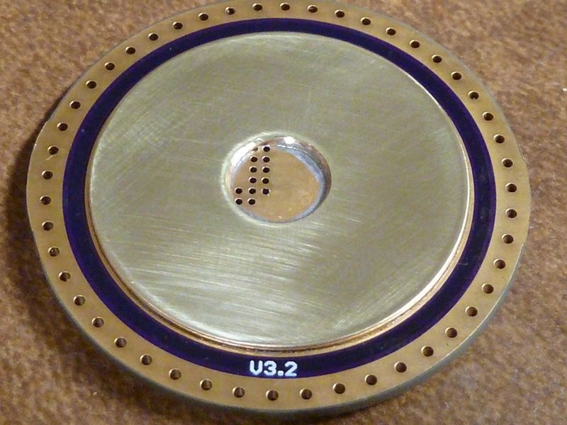
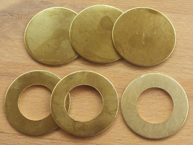
I went with brass for contact rings as well, by the way. More durable, less weight, probably even easier to solder.
Downside of these is they are stamped out, so they are not completely flat. But they are 34mm outer diameter which is perfect for button top cells.
I admit that I prefer not to fill the vias with solder, so I milled a larger center hole and will use a board with LED+ vias inside this ring.
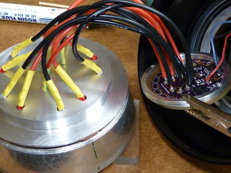
.
 . Wai'tn now for the LDO's.