I started on the mods. First added 22 AWG spring bypasses:
Then some minor changes to lessen resistance for the screws for mounting the spring PCB board. Sanded off the anodizing to make contact with the conductive surface of the PCB:
Replaced steel screws with brass ones, and NO-OX-ID treatment:
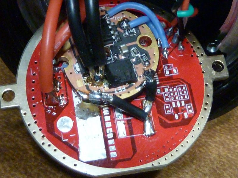
Couldn't measure any noticeable difference in output. With the stock driver, the batteries were not a bottleneck, but with a direct FET based driver replacement, these mods will all help. Was hoping I could keep the charging in tact but there's too many interconnected singles - I counted 3 between the driver MCU and the charging controller.
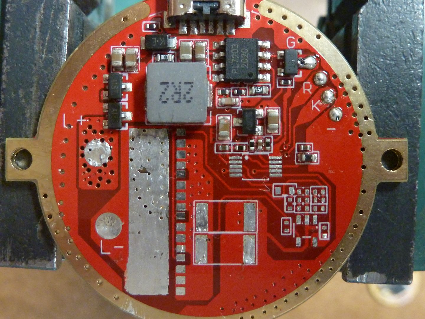
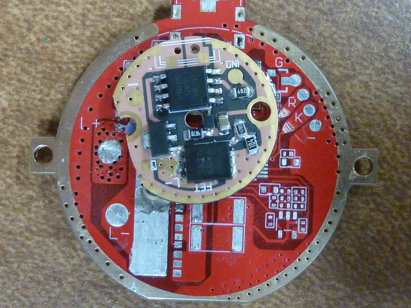
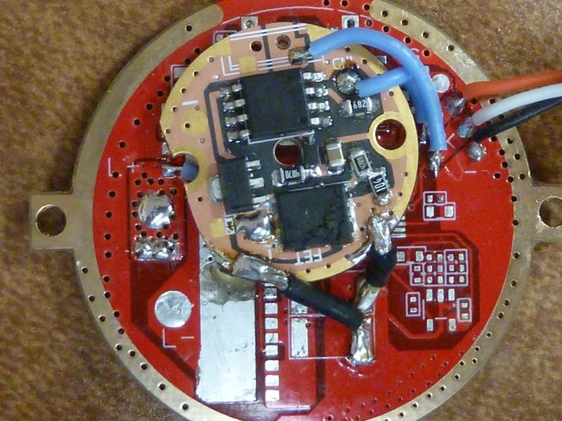
So, this is what it ended up as. All surface mounts removed, piggybacked FET+1 driver. There's plenty of clearance for the mounted board. I used a good quality 2 part epoxy to mount, keep it insulated from the lower driver board. Notice the new pads I created on the R and K pads? This is for the RED switch LED and switch to wire from the new driver to the old driver. There's a blue 28 AWG to connect batt+ to the new driver - doesn't need much in power, the batt+ wire to the LED's will be 18 AWG
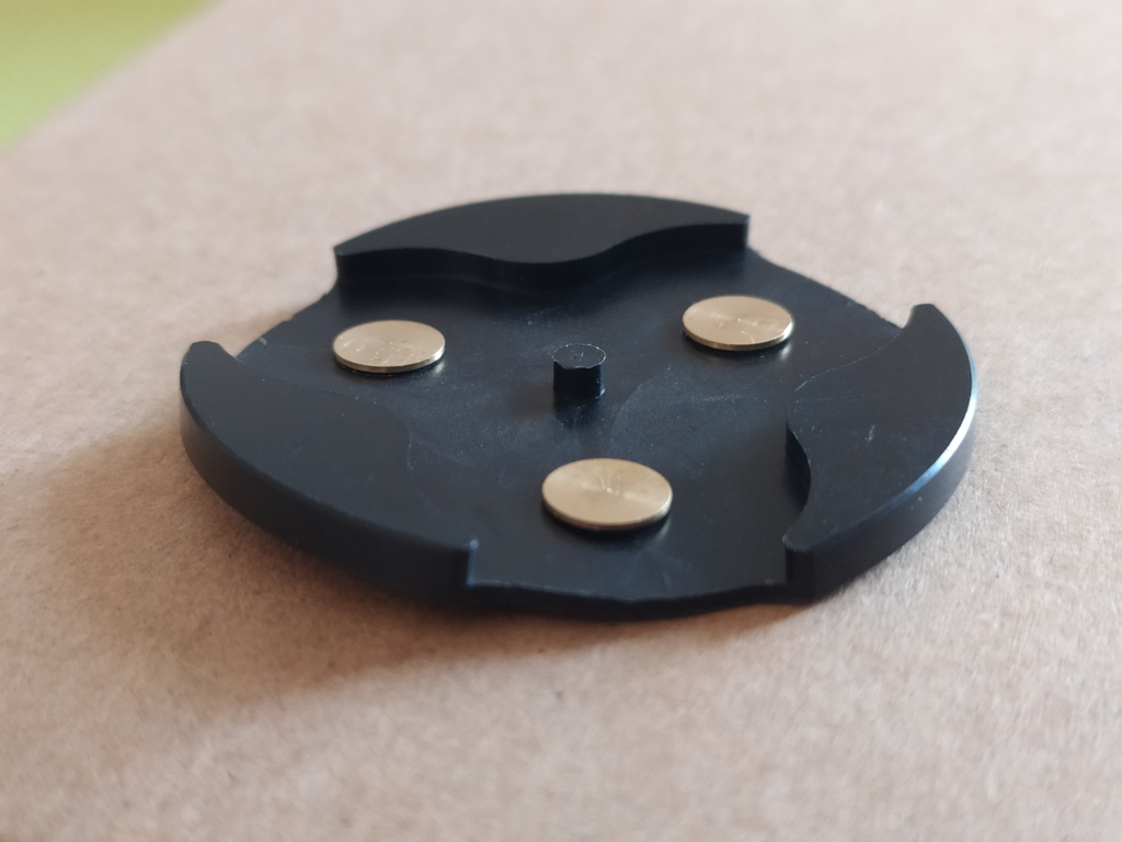
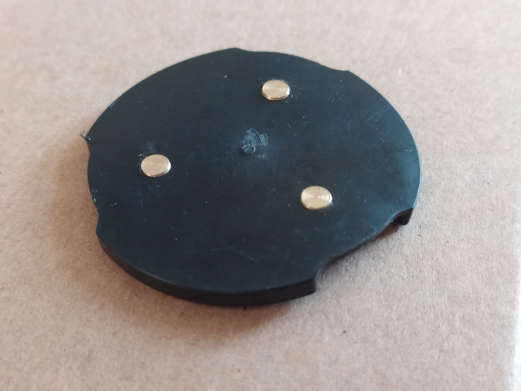
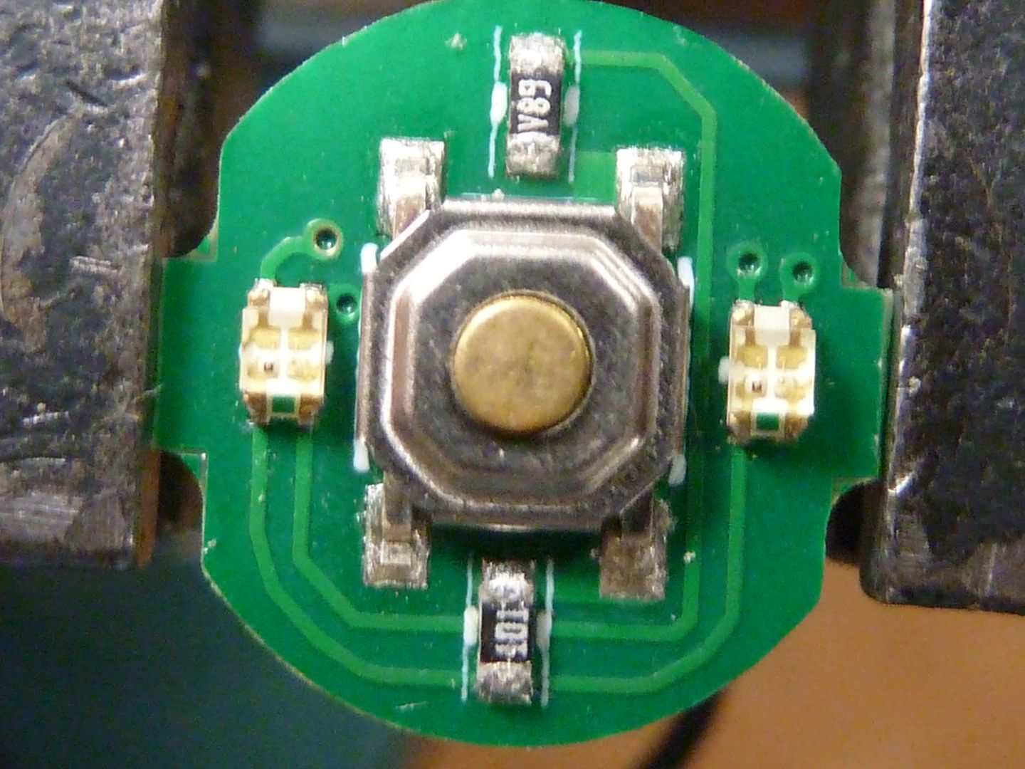
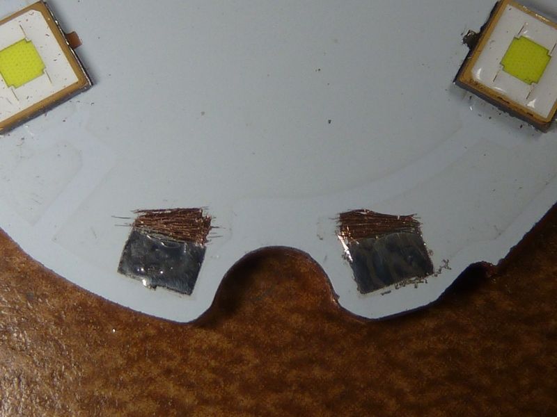
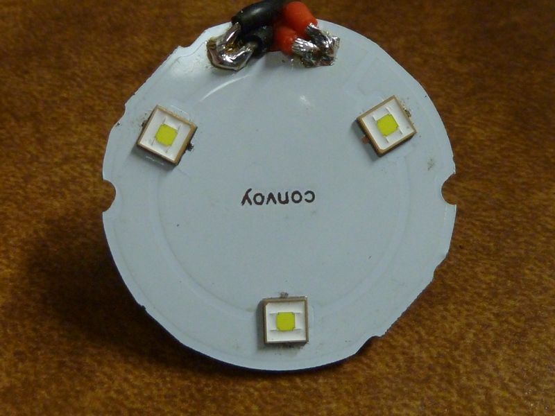
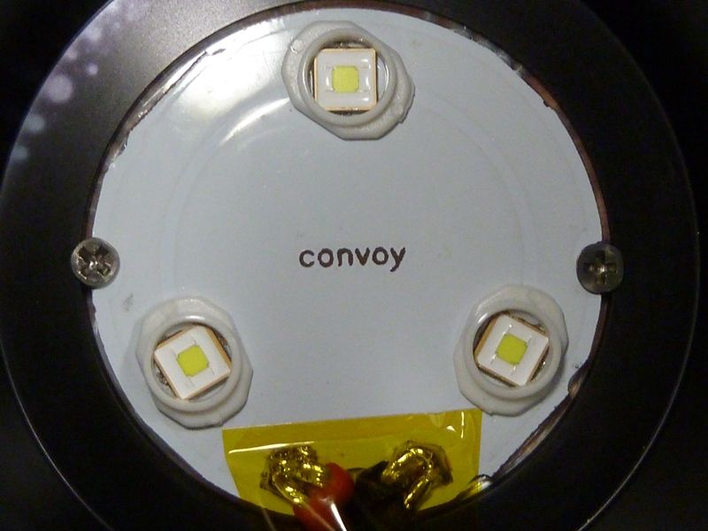
Here's the switch PCB. Small resistors for RED and GREEN LED's (100/500 ohm), but I'll only use the RED's. Somewhat odd they chose to use 2 RED LED's and only 1 GREN LED. The SMD LED's are dual color.
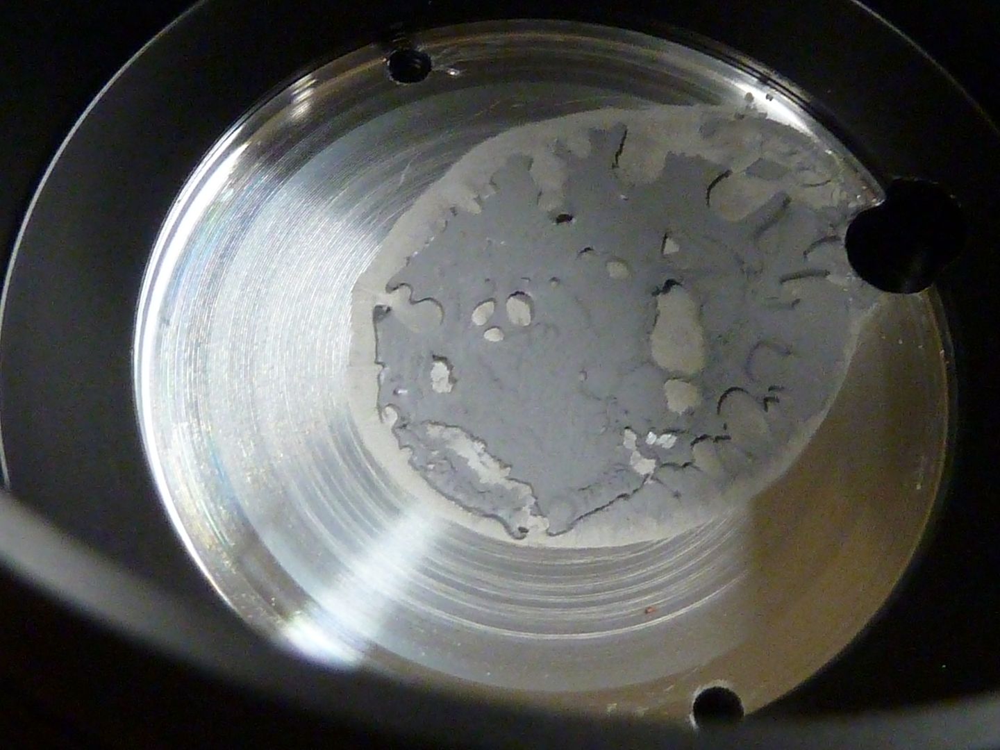
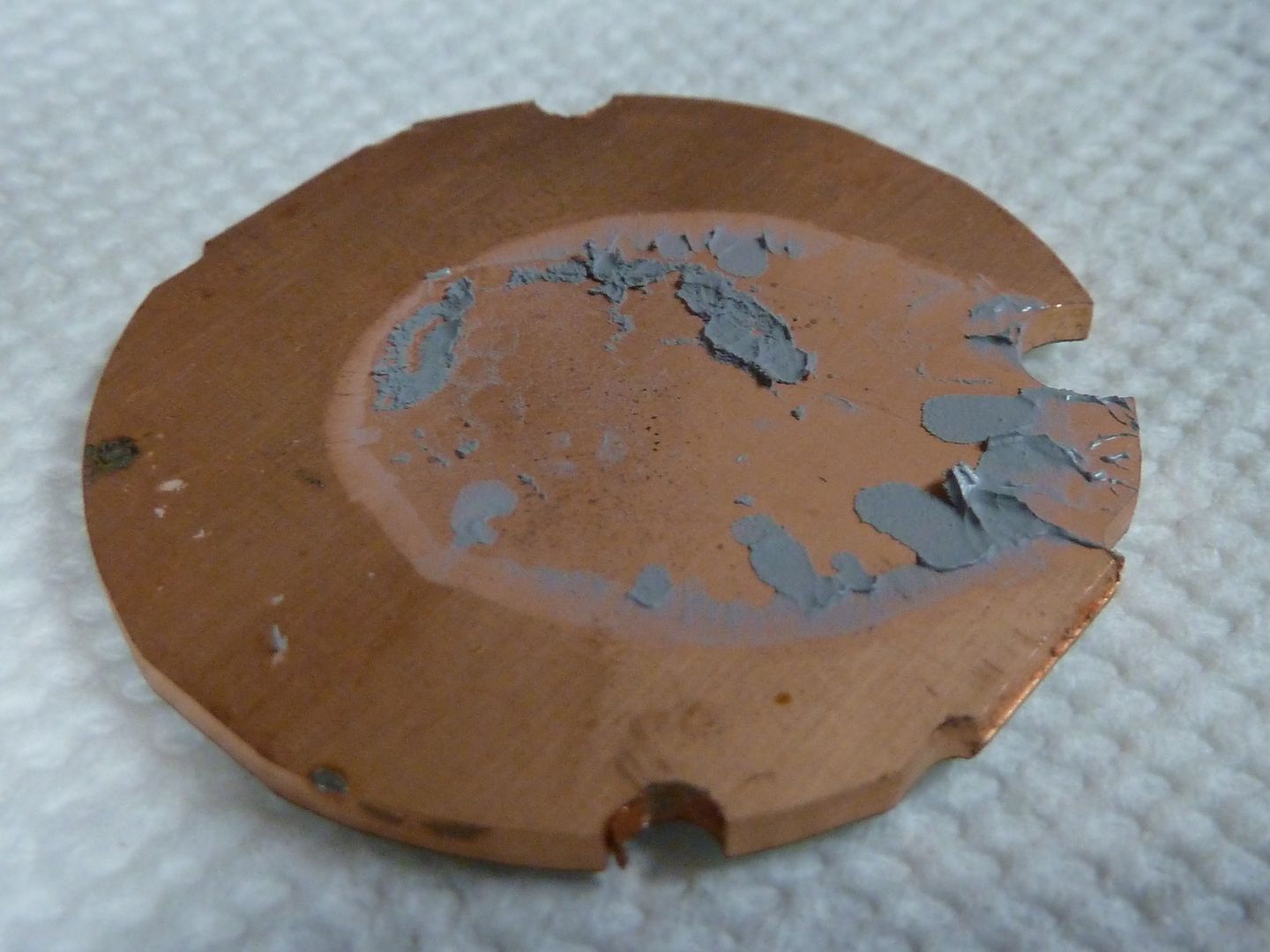
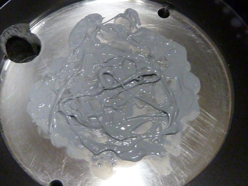
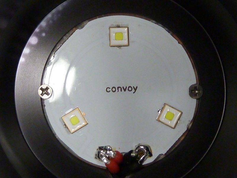
This is somewhat disappointing. The grease is as thick as silly putty and doesn't spread, even when secured down by screws. I hope the surfaces are flat, and the MCPCB has some contaminants on it. This will get a sanding treatment and MX-4:
That's it for now..
2021-07-27 - continue on, and completed the full mod.
Cleaned up MCPCB:
.JPG)
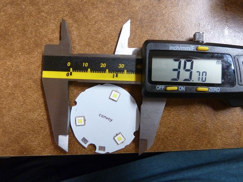
Nice size:
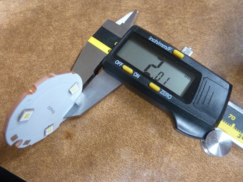
Excellent thickness:
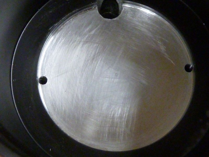
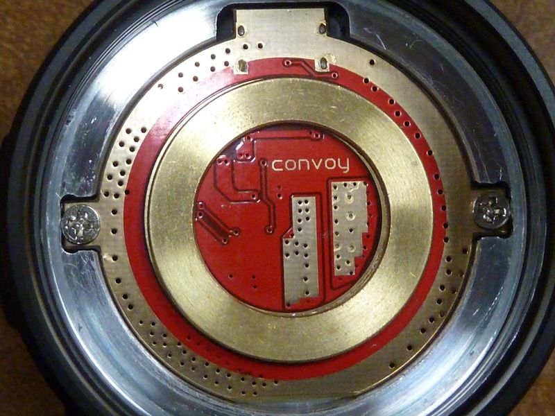
Shelf cleaned up before sanding:
.JPG)
After sanding:
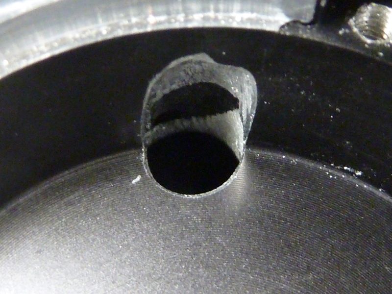
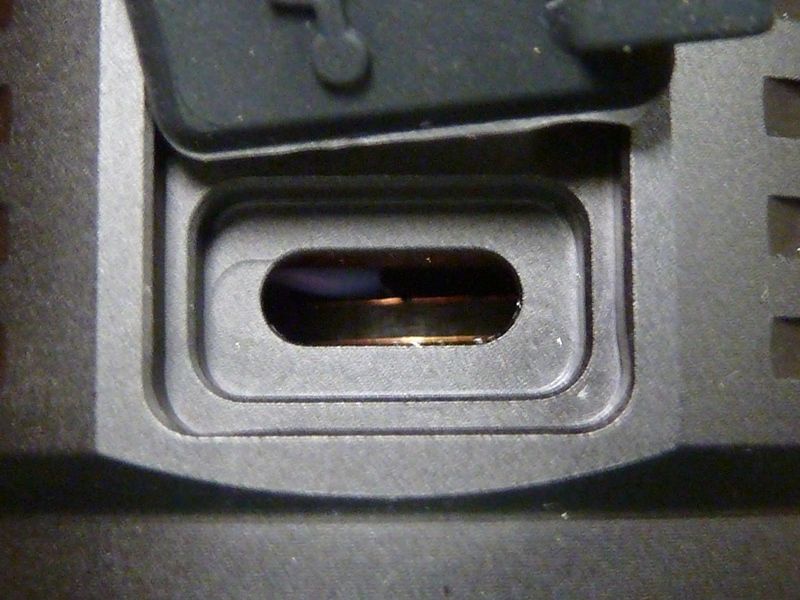
I enlarged the wire hole, using a metal grinding tip on my rotary tool, here shown from below. It made a big difference. I can now fit either 16 AWG or 2 pairs of 18 AWG without a sharp bend, like it had stock:
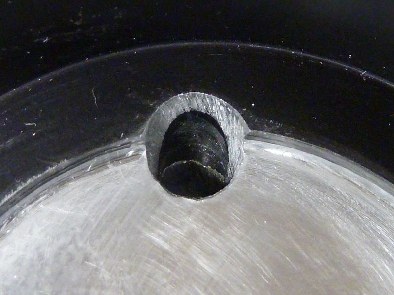
Now from above:
Also I enlarged the pads on the PCMCB. Looks like the reflector had clearance for it:
Here's the driver with all wires except the main LED pairs. I tested it out in this form by adding temp LED wires. Notice I tinned the pads and added a 2nd pad for the LED+. Blue wires are 28 AWG, black batt- wires are 20 AWG:
Decided to go with 2 pairs of 18 AWG. The 16 AWG is a lot stiffer and was concerned about the thin small pad for the LED- wire on the small driver. The 2 18 AWG wires should be more flexible, less stress. Had to dremel the wire opening a little on the MCPCB:
Time for the final assembly. Using MX-4, I wanted to concentrate it in the middle and verify it spreads out when assembled:
Wires inserted, carefully pushing down the MCPCB into place:
Last view of the driver with all the wires. Made the pair of 18 AWG little longer than stock so I had room to work with. The 2 LED- wires were a tight squeeze:
View from above, screws tightened down. I can see some of the MX-4 oozing out - good sign:
Assembled view from the backside:
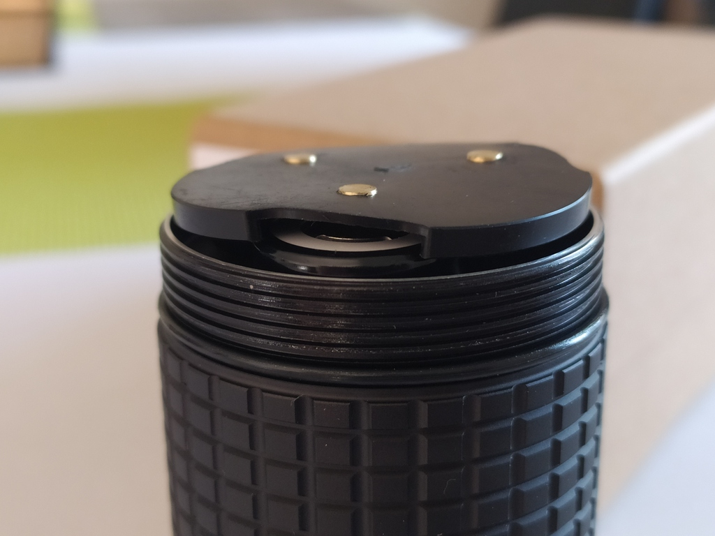
USB-C connector is now gone, giving you a view of the piggybacked driver edge:
Kapton tape applied just-in-case, and stock centering pieces. Was thinking of sanding them down but didn't yet. It can help or make it worse:
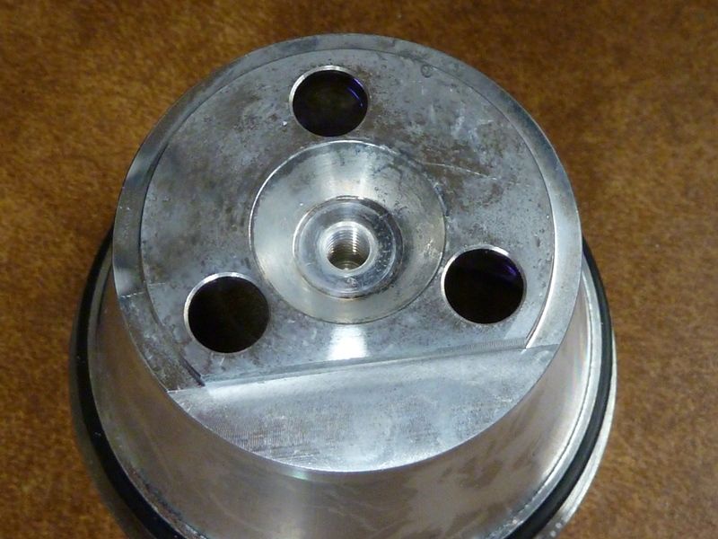
The reflector is notched out to allow space for the wires:
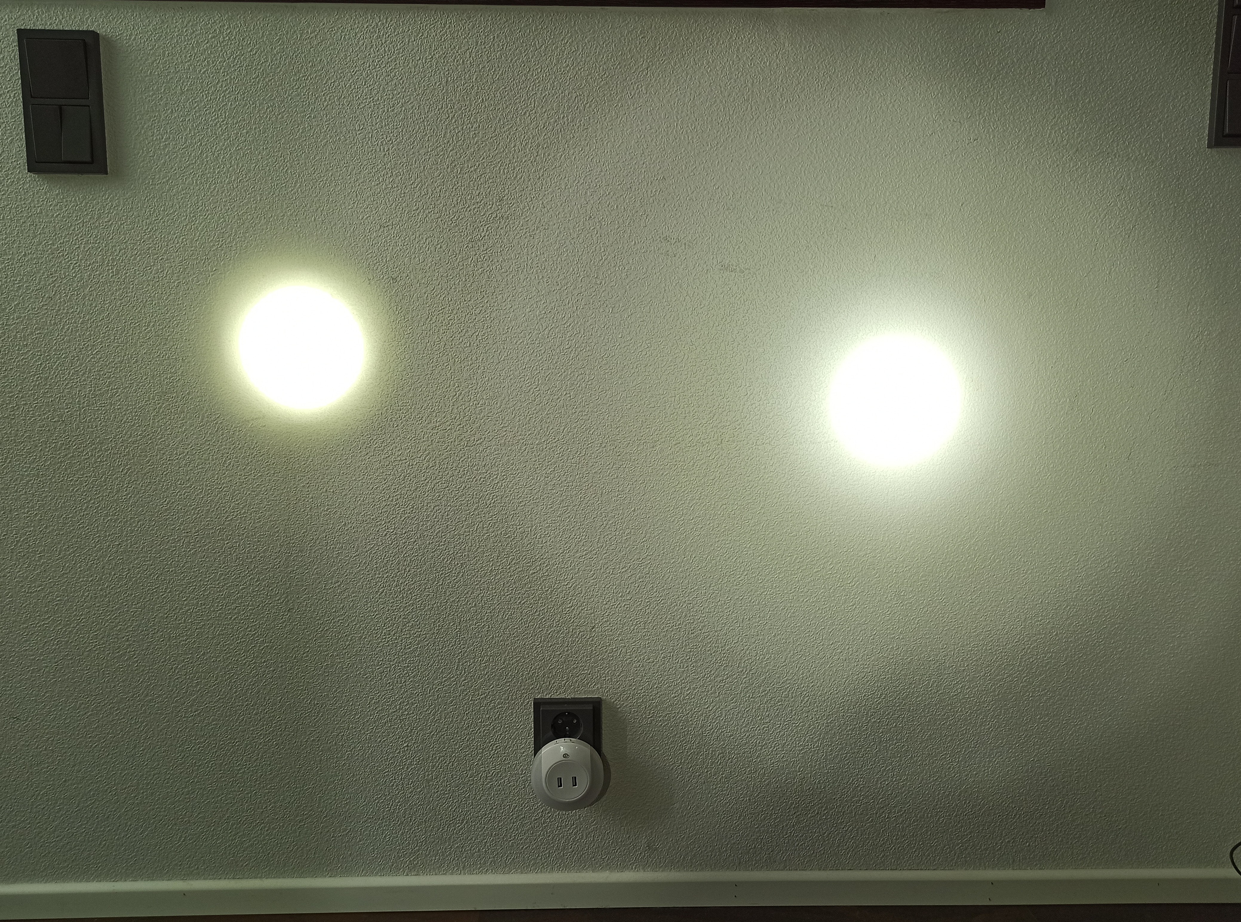
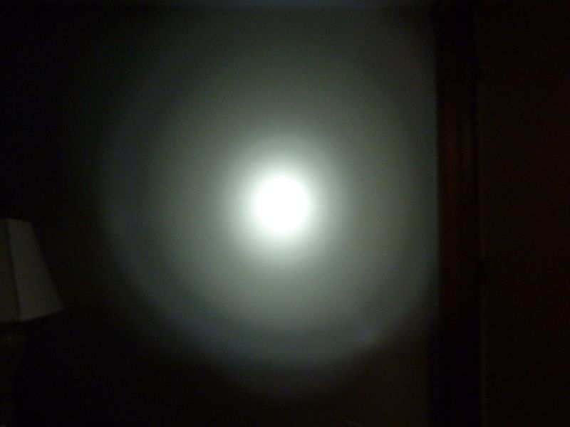
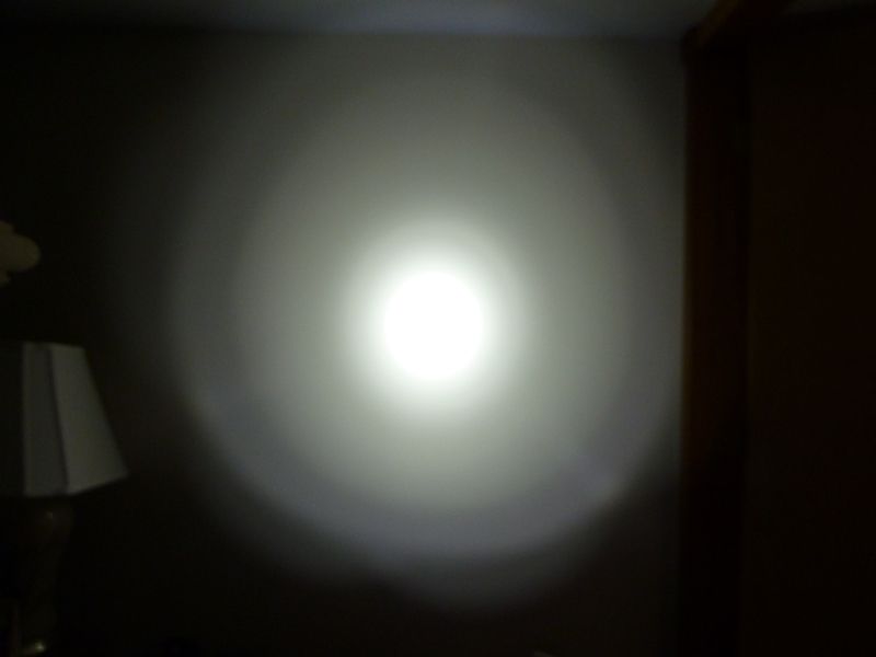
Wall shots of the "new" 3X21A. As you can see, the beam color is all over the place. My camera only does auto white balance, high output:
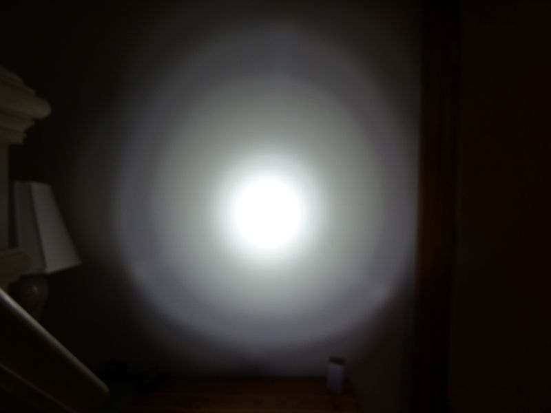
Low output:
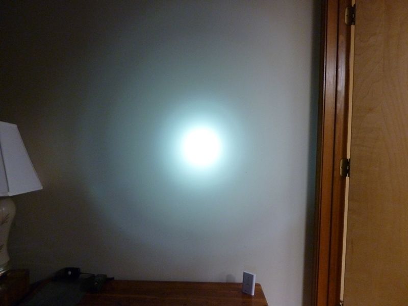
So pick your color - white, blue, green! 
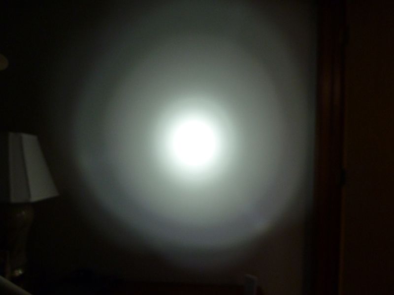
Fiddling with some camera settings:
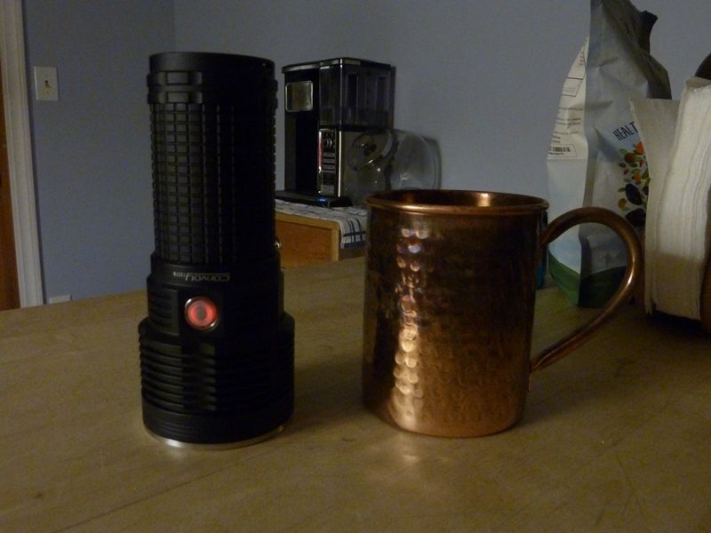
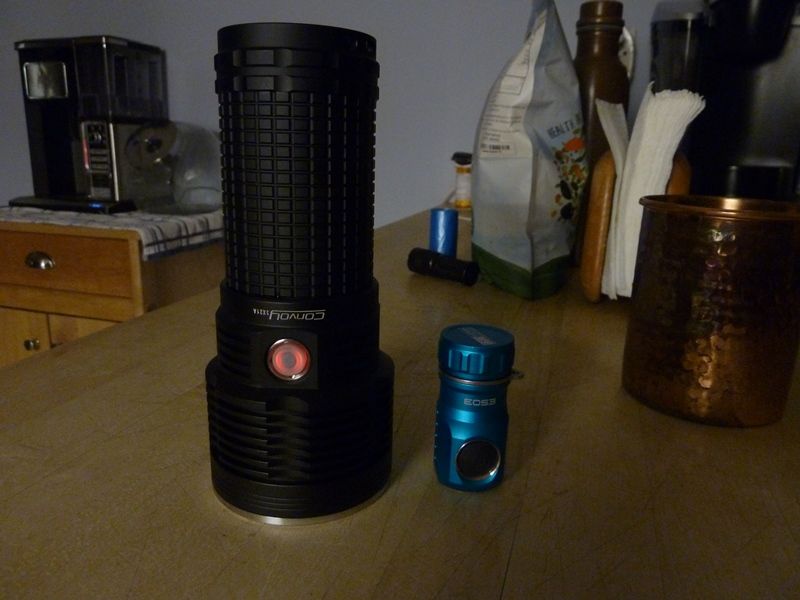
It's a nice looking flashlight, even better look'n now with the switch LED controlled by Anduril2 
New Measurements
I wasn't 100% careful in taking these #'s, didn't have the light meter at the right scale initially, and when I changed it, I recorded that # as the start number. Also my timing might have been off by a couple seconds.
- lumens: on charged 40T solder tops: 7330 at start, 6180 at 10 secs, 6000 at 30 secs (mauuka calibrated #'s)
- throw: taken at 5 m indoors: 335 kcd (1158 meters)
It's certainly a nice bump. Looks like a fast drop over the first 5 secs or so, but very stable slow drop from 10 secs to 30 secs. It's a well designed host, plenty of size for these hot new LED's.
2021-07-28 - another set of measurements, more complete, thorough
- amps measured on a single 30T at 4.20V: 24 amps
- lumens: on charged 30T flat tops w/adapter: 7151 at start, 6696 at 10 secs, 6636 at 15 secs, 6424 at 30 secs (mauuka calibrated #'s)
- throw: taken at 5 m indoors: 360 kcd (1200 meters)
- parasitic drain w/switch LED OFF/LOW/HI on a single 30T at 4.20V: 35-90-361 uA
These are significant numbers. With my prior used calibration factor based on manufacturer's ratings, the lumens would be:
- 8024 at start, 7208 at 30 secs
With the mods, the SFT-40 matches or out throws, and exceeds lumens over the 4X18A SBT90.2, based on reviewer's measurements.