You know I already tore the Small Sun ZY-T20, from this thread.
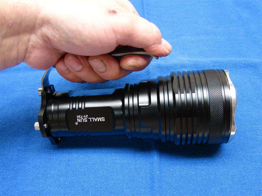
Now it's time to do a little innocent Modding MT-Gangnam style.
Now for the Mod...
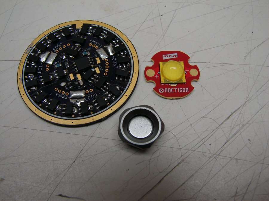
The idea is that I have wanted to do a large reflector light with a MT-G2 running at 9+ Amps. I finally decided to go ahead and do one. I have a driver from texaspyro and I figured Why Not? Why take three NANJG drivers and do all that wiring, just do this one. Well, I have been communicating with tp about it and it probably can be done, but there's some give and take there. I have to put in a momentary SMD switch and I have to do the diode/resistor mod. I will loose battery monitoring and low battery cut out, but I can keep the stock tail switch in the circuit, to provide a shut off that will keep from having parasitic drain, so I'm going for it.
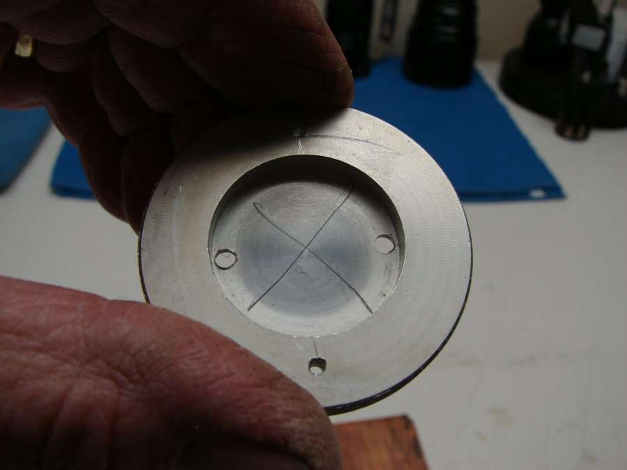
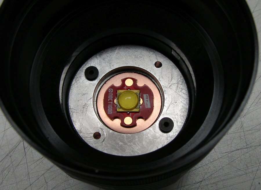
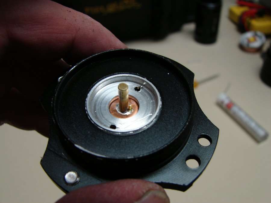
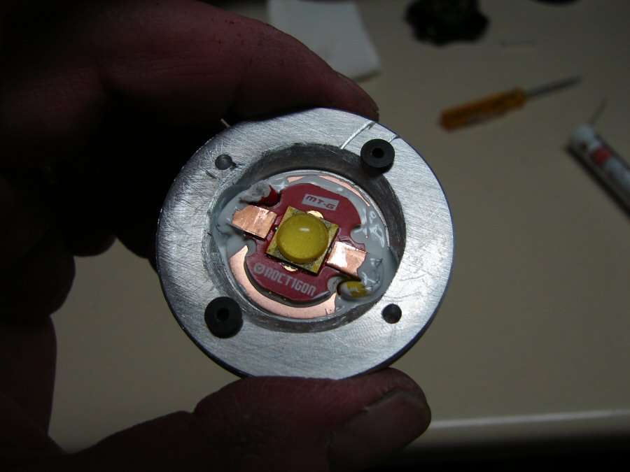
One of the "first problems" is the aluminum heat sink, which I call a led shelf, because it's not really what I think of as a heat sink. I don't believe I want an MT-G2 at 9 amps sitting on this, so I will be cutting out where X marks the spot and using Copper discs in place of that area.
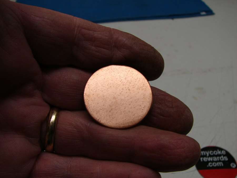
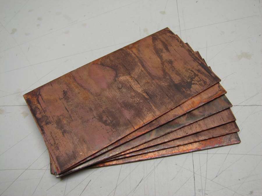
But... I think I need much more than that, so here are Six 1" Copper pipe couplings that have been heated to soften them, split apart and flattened with a mallet.

You can see that I can get two discs out of each coupling, so I will have 12 of them under the modified original led shelf. I should end up with about a 42mm diameter x 15mm thick Copper heat sink, when I cut all those out and solder them together. With the copper star, copper discs in the Aluminum heat sink and the copper below all soldered together, it should provide some real heat sinking.
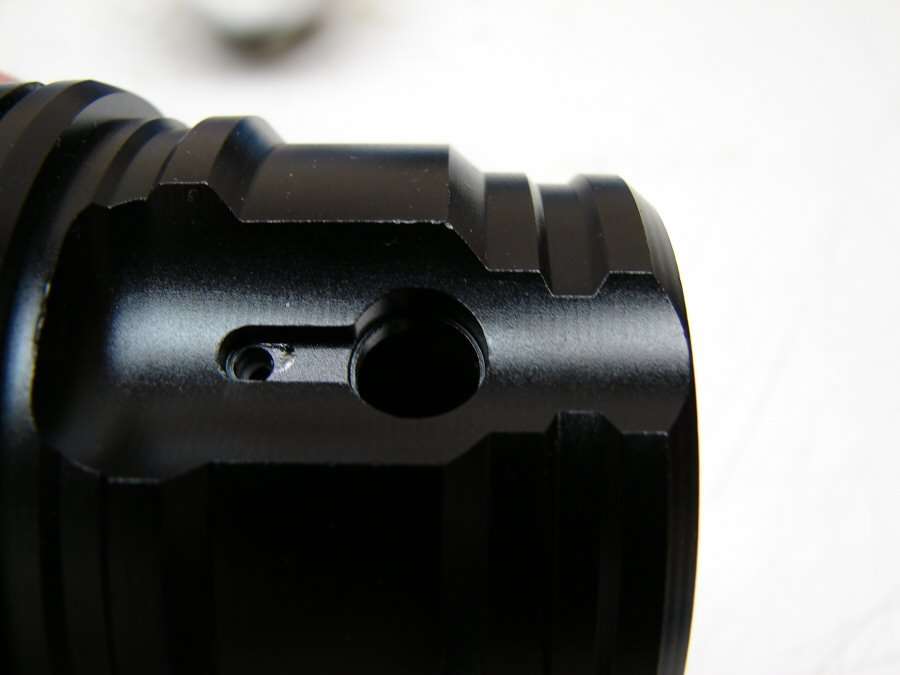
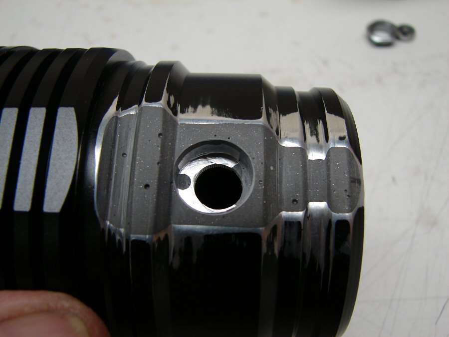
The next of the "first problems", is the fact that I have to put in a SMD switch and housing. This hole looks like it would be great for it...
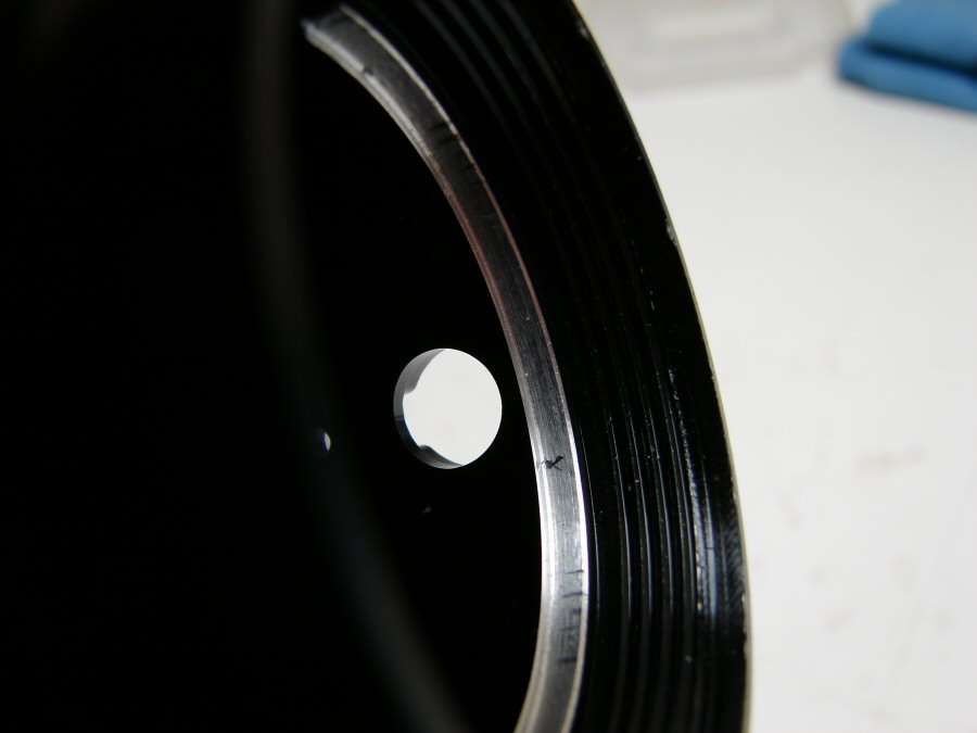
Well, not quite, as you can see on the inside. It is very close to the driver mount and I have to make it bigger yet, for the switch. I may not be able to do it at all here and it is also 180 degrees away from the top of the light when holding it by the handle, so I would have to solve that issue too. I may have to just blow a new hole into the other side of the head, to make it work. One way or another, it will work.
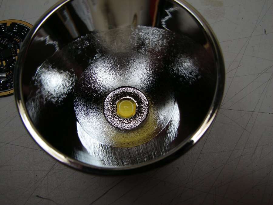
The third of the "first problems", is the reflector. It already has a hole big enough to let the dome thru, but I believe I will find that in order to get any kind of a tight spot, I will have to open that hole up so I can sink the reflector down around the led, flush with the star. I will have to set up a testing spot, so I can power the led up and see if I have to lower it.
----------------------------------------------------------------------------------------------------
11-23-13 - I spent 8 hours in the shop and I really don't have a thing to show for it. Sometimes hand work just seems futile, but here is what I accomplished in all that time.
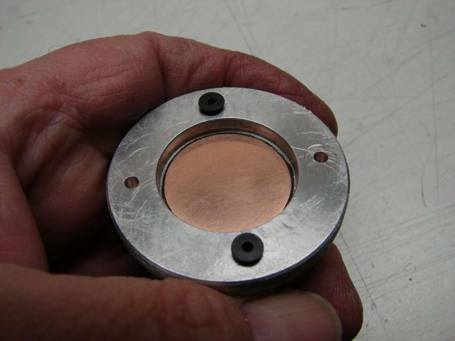
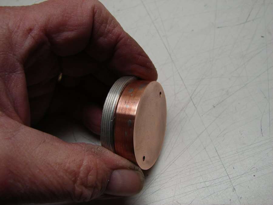
It took the whole day to make the Copper heat sink. 12 layers of the flat plate made out of pipe couplings, all soldered together and made into a round that fits snug into the head. Three Copper discs that go on top for the LED star to sit on. Opened up the original aluminum shelf, so it is now just threads, so the heat sink will screw in like original. I am not going to solder the star to the heat sink. I want to be able to get it off easily when it fries after continued 9 amp use. The heat sink weighs 170 grams or 6 oz. The head, with the heat sink in, weighs 462 grams or 1.03 lbs. Next up will be testing the reflector to the led and figuring out the necessary height, to get the best hot spot, but not tonight, or tomorrow either. With the cold front that has come in, the garage is not much fun to be in and I have to do some honey do's tomorrow, like steam cleaning the carpets.
---------------------------------------------------------------------------------------------------------------------
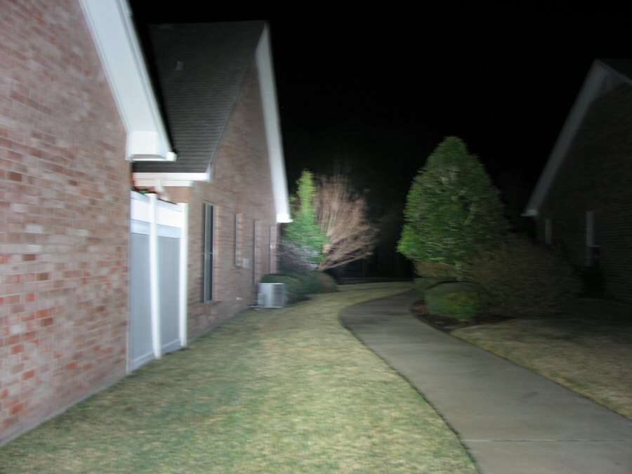
11-24-13 - It's Cold! I know, it's T shirt weather for yous yankees, but after living down here for many years, it's cold whenever it's below 50 and it's well below that. I don't have a lot for you today. I did hook up the MT-G2 to 4xAlkaline AA batteries and fired it off, so I could sit the reflector on it and see what the beam will be like. I really can't adjust the reflector height, so here's a couple of shots with it sitting as it will in the light.
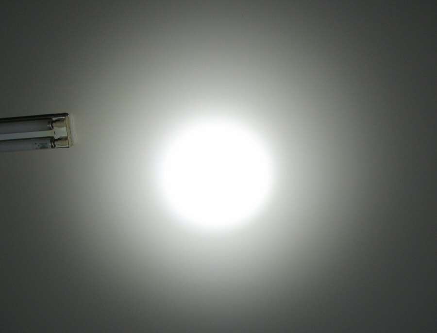
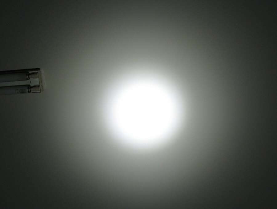
One shot is at a faster shutter speed than the other, to see the hot spot more clearly. One thing I will say is that the half stippled reflector does seem to really help get rid of the dreaded dark spots in the center of the beam, which I see in every MT-G2.
I also have been debating on what the hell I am going to do with the switch and today I decided that no matter what, I had to fill in the original area that was milled out for the stock charging port. I ended up going with JB Weld and then I can drill/mill out whatever hole I need for the momentary switch. I picked one switch up from Radio Shack today, but I do not know if I will use it or stick with a Rook switch.
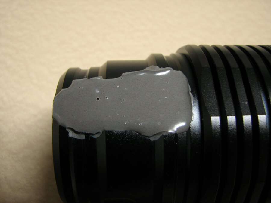
Once it dries, I can start smoothing and blending. When I have it all set and the switch hole is done, I will paint the bottom section of the head with the Black VHT paint.
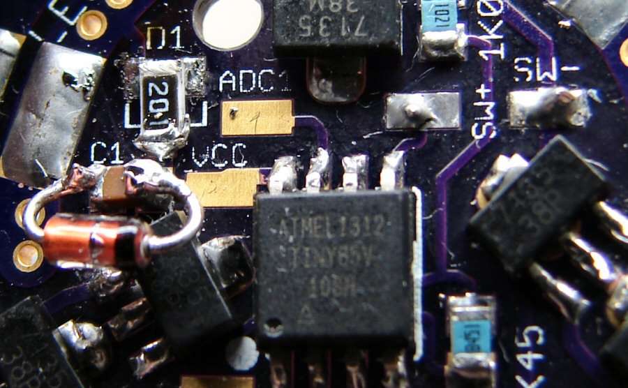
I did the mod for the texaspyro driver today also. Here's a before & after what I did. I think it will work, but time will tell.

----------------------------------------------------------------------------------------------------------
11-27-13
I don't care what anyone else says, It's Cold down here! I'm a wuss after living here for so long. I grew up in harsh winters, with lake effects weather, but after being here for so long, it's cold as heck when it gets to the freezing point here.
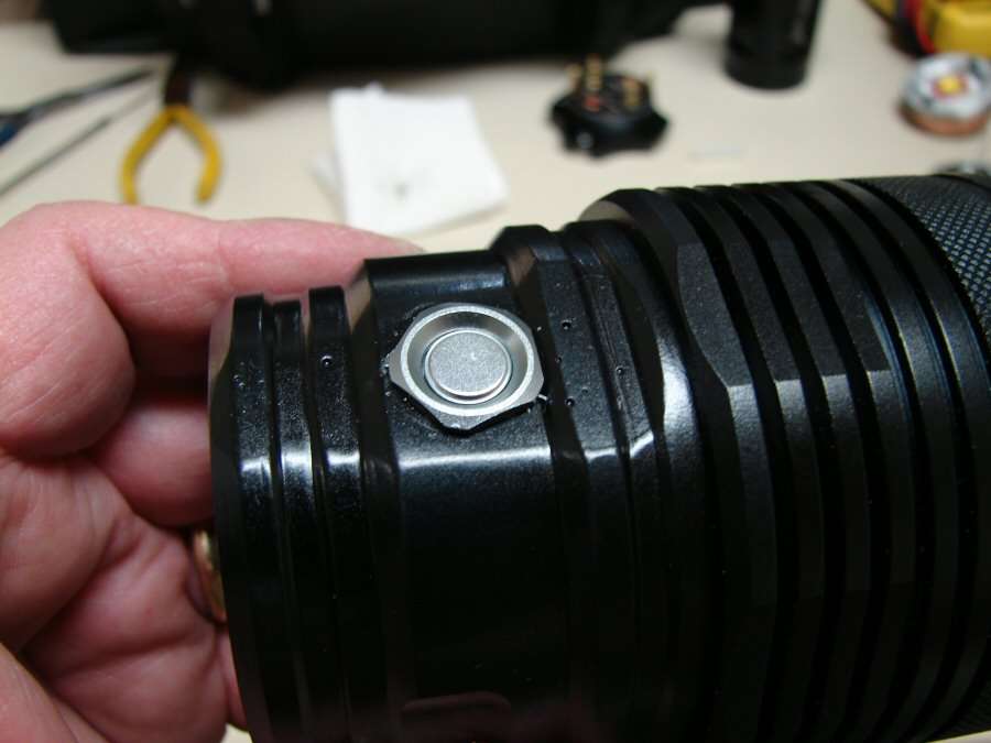
Anyway, I have been doing very little, but I have made some progress. If you remember from an earlier photo, I had filled in part of the head with JB Weld and I have gotten the switch problem solved, (I think).
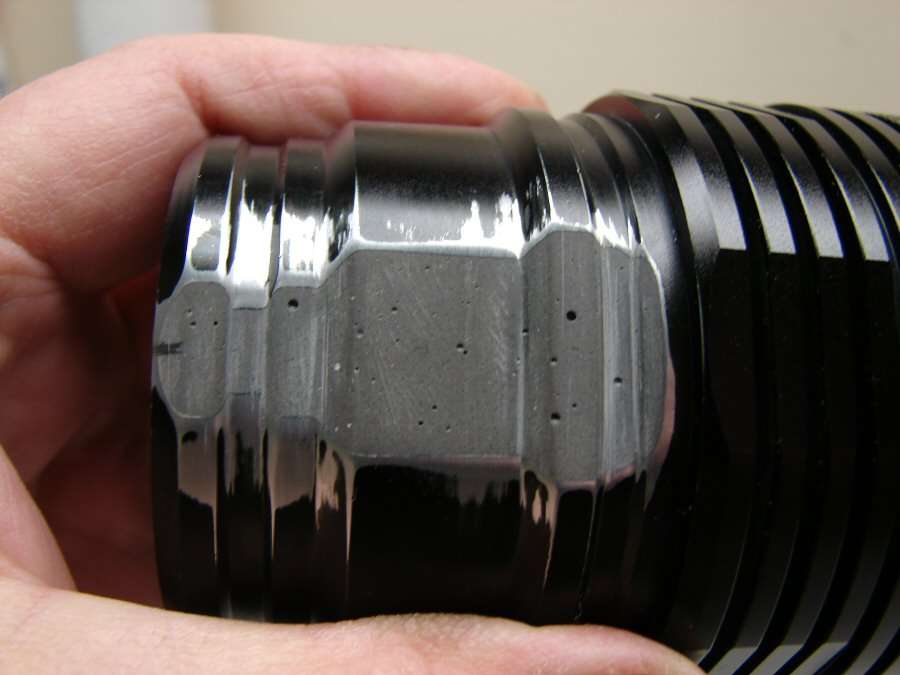
Here's the area after I formed it with files and sandpaper. It came out better than I thought it would. The air holes will be filled before painting.
Then I had to make a hole for the rook switch cover. I started out with the drill press and a couple of dremel bits to make the starter hole, but to make it big enough, I ended up doing the rest of the enlarging and depth, with the head in a vise and using the dremel tool by hand.
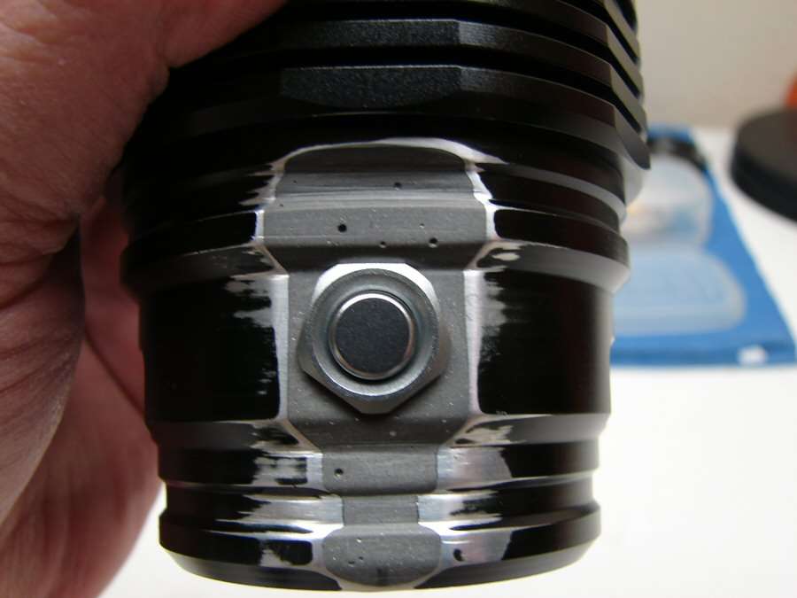
Like I said, it came out better than I could have imagined and I was very worried about the JB Weld breaking up during this endeavor, but it held and it will work. I could not make threads, so the cover will be glued in with epoxy when the whole switch assembly is fit into place.
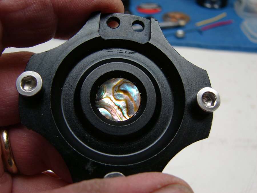
I also gave up on the tail cap switch. I figured out that it would be hard to break both of the 2S/2P circuits and besides, the switch is not rated at 10 amps, so it would most likely fail sooner or later. Instead of the switch, I went with a plug of Abalone shell backed by a couple of metal discs and held in by the original retaining ring inside the TC.
I am also working on modifying the original driver into the contact plate for the 2S/2P battery configuration. I still have a lot to do, but every little bit gets me closer to the final day.
------------------------------------------------------------------------------------------------------
Here's the last of the photos. It's finished.
I decided to rework the circuit path of the batteries. I wanted to load from the tail cap. so I made it into the Caveman style. EA8 that is, with the back contact plate that spins in the tail cap and has alignment studs in it. Here I have soldered a brass pin in the center, so the contact plate will fit over it.
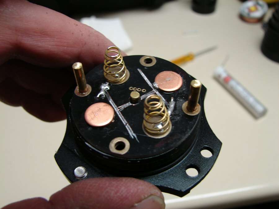
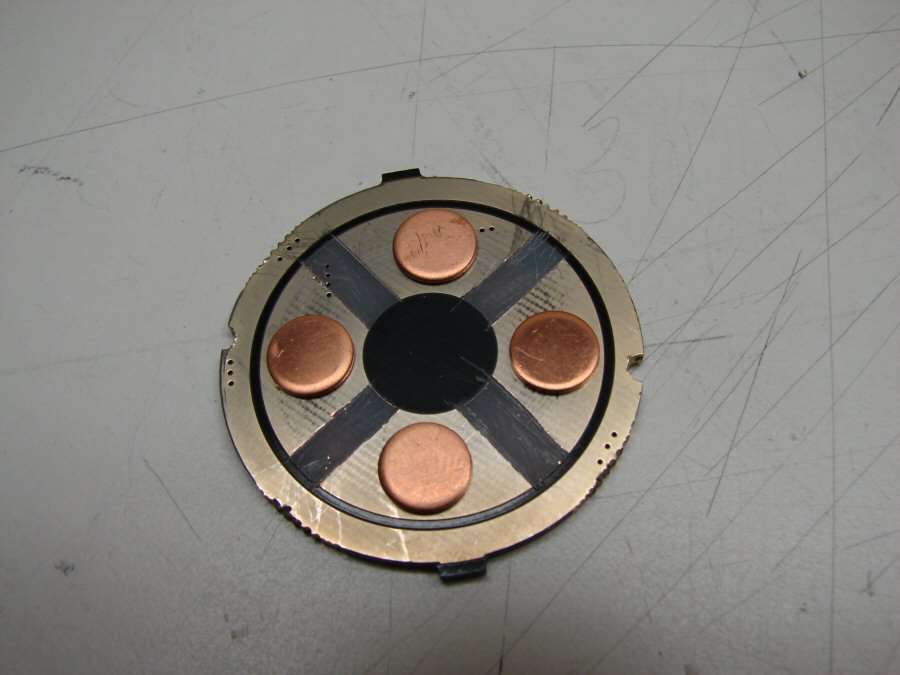
Here's the modified contact plate, with the positive and negative contacts and two guide pins. I drilled the body, for the pins to fit in and align the plate as it is put into place.
The pill is ready. I had to notch the aluminum ring, to clear the wires and I used AA to keep from having any shorts.
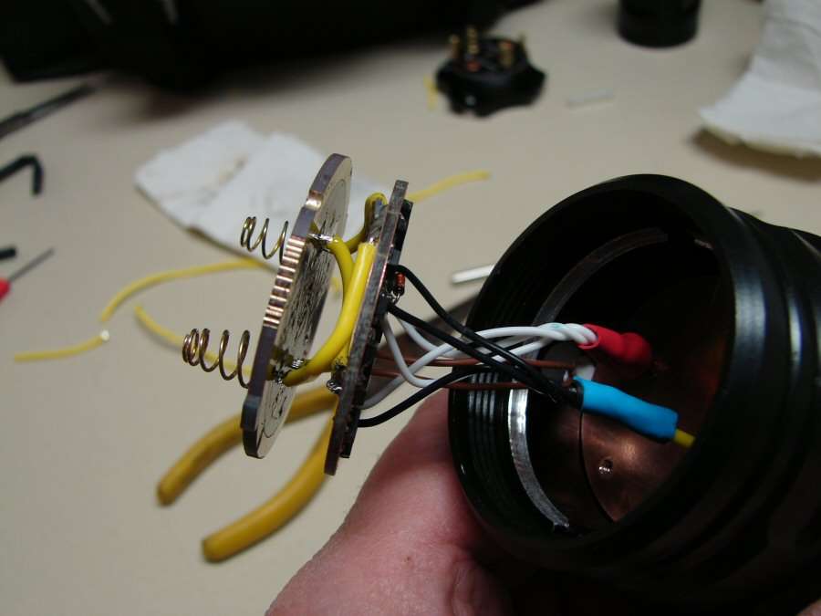
The upper contact plate and driver are all wired up, ready to close it all up and "go for it".
The head was painted and the switch is all done. I forgot to fill in the small holes in the JB weld before I painted. Don't know if I will go back and do any more with it, probably not knowing me.
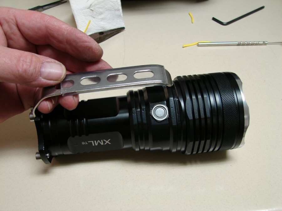
Finished.

Beam Shots:
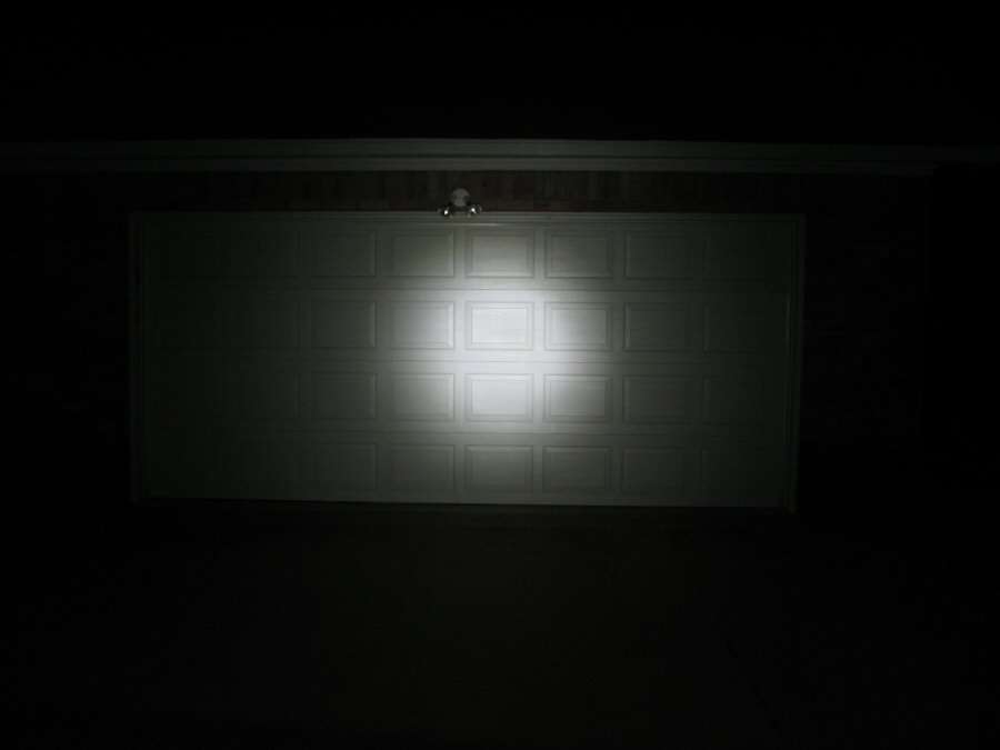
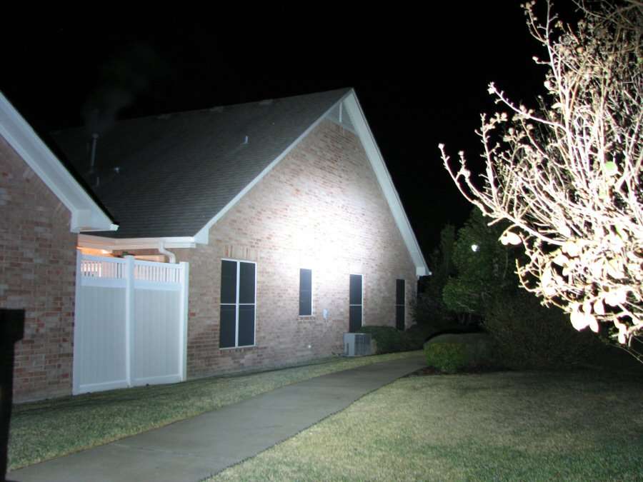
Stopped all the way down to 1/60 of a second, to see the hot spot more clearly. Smooth beam, no little "dots" in the center, like most reflectors have with the MT-G2.
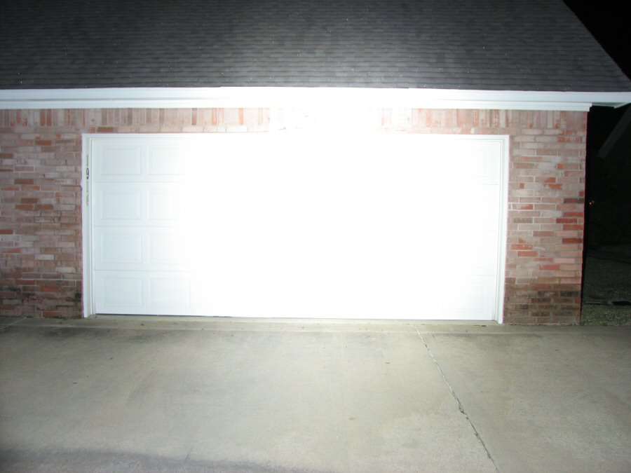
Back at 1 second, it's bright as hell and brighter than any multiple XM-L light I have played with.
Don't move the camera when you take a photo. There is a LOT of spill and it does take away from the center spot. I would imagine the stippled bottom half of the reflector is the reason, but since it got rid of the "holes/dots" in the center spot, I guess I can accept the final overall beam.
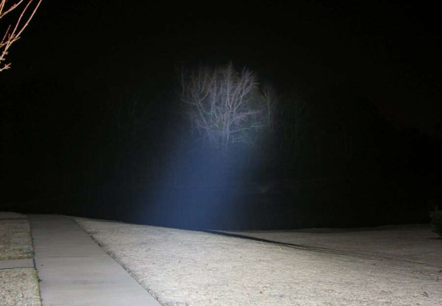
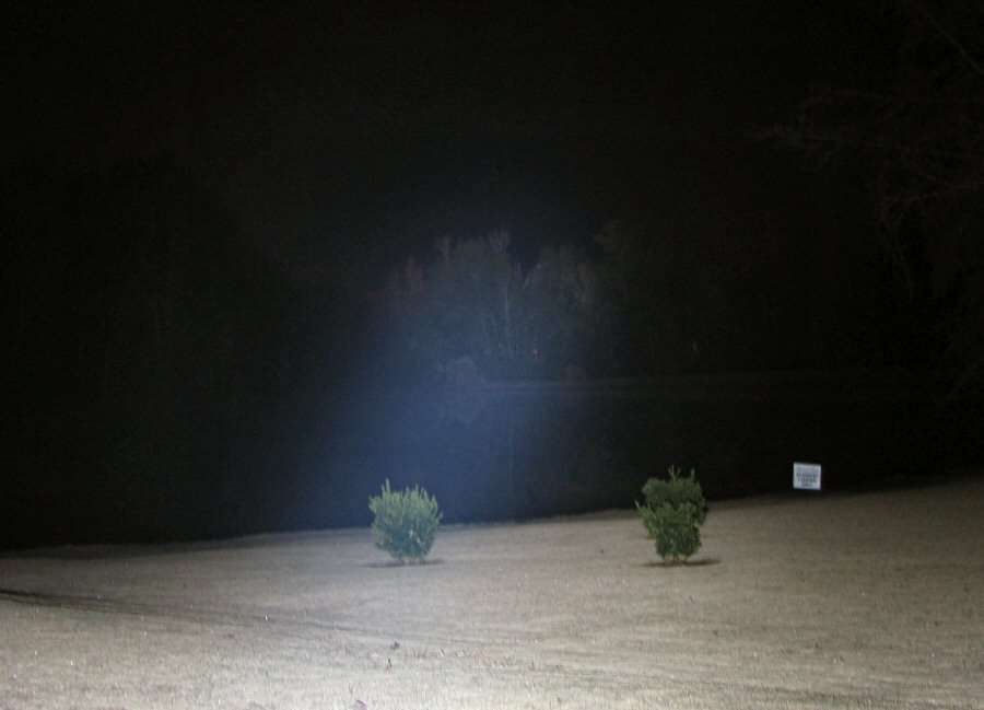
There was a lot of fog over the pond, so it blocked out a lot of the beam. The beam isn't blue either, but it looked that way in the camera, probably because of all the light reflected back from the fog.
That's it.
I have not done amp draws yet and I don't know if I can/will. SInce the circuit is 2s/2p I don't know woh I am going to use the meter in the circuit to read the amps. This circuit does not rely on grounding to the light itself. Since the + and - are both at the same end, (up front), there's no way to ground against the case, or at least it wasn't needed to make it work.
EDIT: I read just about 9 amps on the nose with the 20R batteries, so it's doing what it's supposed to do. Good deal. I still like the SST-90 aspheric better. It's impressive, but I would take a King at 9 amps over this any day. Smaller size and larger hot spot.

 .
.