Wow, that is a great deal on the X6R... They have pretty good deals on the other Eagle Eye's as well, including a X6 with an XP-L HI, A6 hosts, etc. Not many pieces sold of anything though - pretty new store, Mr. Eagle eye...
------------------------
Here is a better ref: https://learn.sparkfun.com/tutorials/voltage-dividers. You can plug in our values for R1 and R2 and see what you get. I believe if you have a 5V source coming in, you need to scale it down to match against the 1.1v reference source.
For our use for LVP now, we want to measure 3V against a 1.1v ref source, so, we use 19000 ohm R1, and 4700 ohm R2, so resulting voltage is 0.59v, which is just a little over 1/2 of 1.1v, correlating to an A-D value of about 130, but have to subtract out voltage for the what the diode takes, so we use a value of 120-125 or so.
To detect the 5V source's presence, maybe a direct wire would work, and maybe it will read 0 or 255 if present, dunno.
Might be one pin free. Dunno bout the 5V going direct in, true, might be a problem, but 5V is within the normal range for these MCU's. I'm kinda learning as we go .
Blf-a6 is one of the most advanced firmwares, and it indeed has a a pin assigned to “star 3” as our fellow member already pointed out. Air wire straight from 5v input with a limiting resistor inline, then set the FW to PWM=0 whenever signal is detected on Star 3. Any reason why that won’t work?
These ATTiny's have 8 pins: RESET, GND, VCC, then the remaining 5 pins are all I/O. Of the 5 pins, 2 can be used for PWM's.
So of the 5:
- PWM out (to FET or 7135's)
- secondary PWM out (if using a FET+1 driver) or available
- LVP in via the voltage divider circuit
- e-switch in
- available (or possible OTC with an e-switch, maybe?)
So for an X6R with e-switch, you could have 2 pins, 1 pin, or none available -- all depending, but none is highly unlikely, only if you use a FET+1 with OTC.
The RESET pin can be used for I/O but once you do that, you can't re-program with our usual $5 USB dongle - needs a special setup to clear it.
Thanks Tom. Looks like this should work for me, just need to figure out the specifics.
At least for my uses I don’t ever need both an OTC and e-switch. On dual-switch lights I want the rear to be only on/off so it can be a forward clicky and capable of signaling.
Hhmm, got the light with me @work, but can't do much here with it. I still have the original piggyback driver though @home - I can work with that, then should be able to measure the main board that hold the charging circuitrly and switch. My 2nd X6R is on the way, think in the country now. Oh boy, hope I can remember this eve....
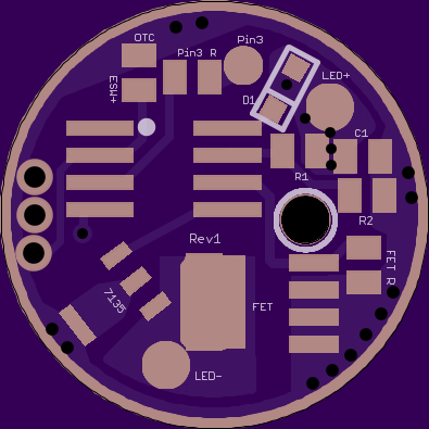
That’s fine. In the mean time, I’ll see if I can get everything else to fit. I was going to add a pad and resistor/diode/cap pad for pin 3, and a pad for your Fet gate-to-ground resistor. Or maybe I’ll forget those, and try to fit the attiny85 instead… we’ll see.
That is sweet. I was planning on designing this very board myself but I’m still in the VERY early stages of using eagle.
This board has everything! Nice work!
Dang, it sure does look nice! Good to have that pass-thru for LED+ - I've been drilling out the LED+ pad on the wight boards. We found out a little more bout the blinky-mooon mode problem - seems to not occur on some FET's, and occurs on others. Still good to have a pad for the resistor though, as you did. From dthoang:
"I just replaced the FET in the Manker A6 with an NXP PSMN6R5-25YLC and confirmed that the turbo-to-moon flash is gone.
The original FET is marked: 3R030 PBm 1429 C7 9145
My replacement is marked: 6R525L PBm 1502 B5 1981
NXP has two variants of the 3R030: PSMN3R0-30YL and PSMN3R0-30YLD. The PSMN3R0-30YL is the older model still in production, so I’m guessing this is what Manker used.
The dynamic characteristics (capacitances and delay times) of the PSMN3R0-30YL are considerably worse than that of the PSMN6R5-25YLC.
We might be seeing the effect of dv/dt turn on as described here and here."