I think what they’re saying is that you need the bleeder resistor, not in the place you had it, but directly to ground, in order to get rid of the ‘next mode’ memory you’re seeing.
I don’t really know it all that well either, just what I and others have experienced. Typically drivers that use an OTC for mode changes need a bleeder resistor between Batt+ and gnd, and other types of drivers may not. The Qlite in stock form does not use an OTC (and may not need a bleeder) , but an OTC is often added to a Qlite to use different firmwares (like guppy, apparently).
It’s definitely a balance. I think your high tail draw was just too much for the 560ohm to “bleed”. So either lower the tail draw (higher value resistors) or use a lower value resistor for the bleeder
Man that looks awesome! I’ll be working with Simon on the possible redesign of the metal switch in the near future but he needs time to get things running smoothly in his new factory first.
If we do redesign it I’m trying to have the internal rubber seal replaced with a translucent material to let the light shine through.
Nice work guys!
emarkd, can you confirm was the 84ma figure a typo? Was it supposed to be 0.84ma? If so, that’s still high, but it makes more sense.
If it’s actually 84ma, I’m wondering if maybe the Rev5 ring is shorting on the metal switch in that S2+, I know it’s really tight up in there with the little switch button.
Hey David thanks for the input but I did try it directly between positive and ground. My original placement on top of C1 caused me to lose mode switching altogether. Still not sure exactly how that worked but the driver became a single-mode driver (on mode 1, moonlight) with the bleeder resistor stacked on C1. I moved it to a place directly between + and GND and my modes worked again, but then it was next-mode memory. I thought by removing it altogether as Matt suggested I could regain “normal” function but that’s not the case.
Thanks PD, but no that was not a typo. I read 84 mA using my trusty old Fluke 76 meter. Its 20 years old now and hasn’t been calibrated since I bought it, but I think its probably still fairly accurate.
There could be some small short in there somewhere, but I don’t think its against the metal switch. I added waterproofing in the form of a disposable nylon glove just below the metal switch so there shouldn’t be any contact there. I’ll check better this evening though.
ok, 84ma is crazy high, the highest I’ve ever measured was just over 1ma I think. There has to be a small short somewhere I think, I don’t think the resistors you said you used would allow anything close to that current. (and I think the tailcap would be ridiculously bright if it were getting that much current through the LEDs). At 84ma, it’ll totally drain a full 800mah cell in about 10 hours.
Agreed PD, that draw is over the top. Solder bridge or maybe problem with braided springs?
You know, now that I’m saying all this I’m starting to doubt myself. My meter has two lead connections for measuring amperage and if I was using the low-amp input, which I should have been, then I actually measured MICROamps. I’m used to dealing with several amps of draw, not microamps, so its very possible that I’m now telling you all a lie. I’ll double-check it tonight but there’s at least a chance that what I read last night was 84 µA without realizing it. :-/
Would 84 µA be too low to be a realistic reading?
ohhh Microamps would make sense, the Rev5 design is very efficient. My most recent build (the M6) was 20.7 microamps
………. but then I would also think the 560ohm bleeder would have worked fine with that level of draw.
This is part of why I don’t sell kits, there’s always something that goes wrong and doesn’t make sense :nerd_face:
Awesome, so lets assume I’m an idiot (not much of a stretch ![]() ) and that my tailcap setup really is pulling 84 µA and is working properly. Then the thought process is that I really need that bleeder resistor on the driver, yes? I’ve already had a 560 in there with no change in behavior. Should I go higher or lower?
) and that my tailcap setup really is pulling 84 µA and is working properly. Then the thought process is that I really need that bleeder resistor on the driver, yes? I’ve already had a 560 in there with no change in behavior. Should I go higher or lower?
The “next-mode” behavior suggests you still need the bleeder, and still lower value than 560
Lower, got it. I wish I understood why I need a lower one but honestly I don’t. That’s okay though, I’m learning and I really appreciate you holding my hand through this ![]()
I’ll report back later this evening after some experimentation.
I’m no electrical engineer, but the way I think of it is that to make the driver work normally, we have to make it oblivious that the illuminated tailcap exists. So we want all of the power the tailcap needs to bypass the driver and just come from the bleeder. If the driver is still messing up, it must mean that not enough power is coming from the bleeder, and it must be pulling some through the driver, keeping the mcu awake or keeping the OTC charged instead of draining like it should. So we need to lower the resistance to make more go through the bleeder.
I hate to muddy up this thread with a post that doesn’t contribute in any way… but I just gotta say, holy wow have I learned a lot in the last two pages!
Ordering parts Trying to order parts as we speak, I wanna play too! Thank you guys!
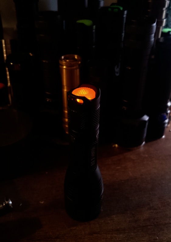
Okay, I got home shortly ago and make some quick progress. I dropped in several different sizes of bleeder resistor, just working my way down through the assortment I own. I got to 220 ohms but then my driver started working properly again! Tailcap draw is way up, 944 µA now, and the tailcap brightness is much higher too, so I may crack the tail back open and increase those resistors a bit. If I understand things that shouldn’t affect the driver though, so hopefully I won’t have to touch it again!
We’re getting there! Thanks a lot PD and others!
That is kind of high. And current going through the driver may be keeping the OTC from draining or could be keeping the SRAM from decaying to its powered-off state. Either of these can break the interface on an offtime-based driver.
I’m not entirely sure how guppydrv (guppy2drv) works, but DrJones’ page says it uses off-time memory. So, it probably needs a bleeder to let power through without keeping the rest of the driver lit up.
It seems you’ve already figured this out though, and are in the process of fine-tuning it. I can at least say that the lower the tailcap power, the less the offtime-disrupting effect. Also, the less-resistive the bleeder, the lower the offtime-disrupting effect. However, less-resistive bleeders also make the normal running modes less efficient, IIRC. So, it should probably be the highest value which still works.
Hehh. I would avoid getting too excited. Very little of that has been fully thought out. :-/
The 84mA number was a mistake - turned out to be 84uA, much lower. The bleeder isn’t hurting the efficiency in regular modes very much. For example:
4.2v / 200ohms = 0.021amps
So in the case of a 200 ohm resistor: with the light turned on we’d be wasting 21mA constantly through the resistor if the battery maintained 4.2v (which it doesn’t). That’s less than 1/10w, which is probably quite a bit for a little 0805 resistor… but definitely not too much I think.
Your observations seem accurate. This is a pretty weird thing to be doing to the overall circuit; I think that your assessment is close enough to the truth to run with.
I’ve had that issue, with pot boards, and once you dial in the leds so the modes/memory works right, you’ll run into issues with the light after it heats up, even just warms up. I was using guppy but decided to build a few blf a6(+7135) drivers for a change, and the same happens. Also attempted lighted tailcaps the same way you did with a 3.04A qlite, same outcome as you experienced, I pulled the lighted parts and gave up on that because it was just to try it. Ive put the bleeder on the +spring to ground, and on top of the OTC cap, from otc to gnd, I have no idea what could be going on here.
Could the bleeder resistor and the led resistor in series acting as a voltage divider be something we aren’t taking into account?
When the light is off we are putting +470/560/200 ohms worth of positive power into the host, when we turn the light on we overpower that with - power making the host more neutral than the bleeder resistors bleed off, killing the tail leds and not losing any power at all from the main led(s).
Maybe we need a diode in series with the bleeder? Or is there already one lined up with c1? Or maybe there should be one in line with the OTC cap to keep power from backfeeding when the light is off? It seems like power is backfeeding into the mcu or a component causing it to get heated and mess with the modes.
I measured the voltage at the tail leds set up with blf a6/mtn17ddM/470ohm resistor/.67mA draw and it was only 2.1 V, same light before without any lighted tailcap parts it was 4.2v & .06mA draw.
I really don’t know, I’m just spitballing what I’ve done hoping someone with actual knowledge can say “hey dummy do this…” I’ll try about anything.
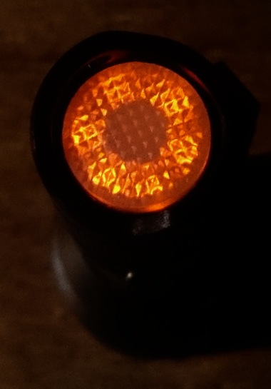
I got the alu X5 in today (what a great little light! The bling of the CU/SS set was nice, but IMHO this little black X5 is what this GB was all about) and since I received the 6-led dumb board as well this week, I could not resist instantly modding it. Pulled out the blue led tail assembly and build a new one from the 6-led ring, a new small Omten switch and a BLF-A6 switch board that had come spare. The resistor before the single blue led in the stock light was 2K Ohm, so I did not dare to go different in fear of messing up the driver UI: 3x 6.8K Ohm parallel for the new board, 6 orange leds. It all worked very well and I also reflowed another led: XP-L Hi 3000K 80CRI for added cuteness. :-)
Happy camper. Thanks PD68 for another winning design! 

Looks very nice djozz.
I’m interested in installing a Rev5.1b in the S2+ and Solarforce tailcaps. Will that 19mm PCB fit in either?