New Update - the saga of the O-L BLF Limited Edition Maglite This is just an FYI

Well, I have been thinking a lot on this limited edition light and I have a couple things to go over with you.

First off, I have a logo here and I have a sample light coming, which I will post photos of, when it arrives.

logo1

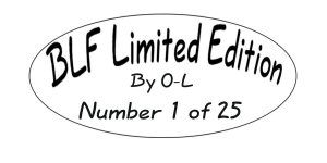
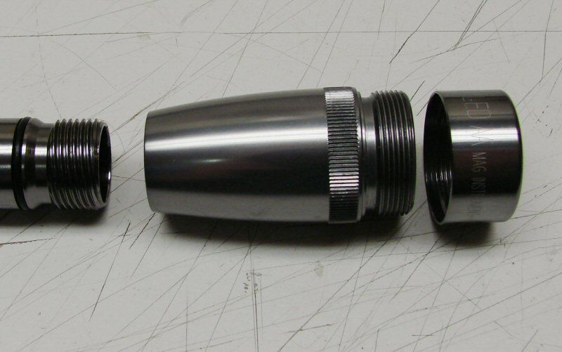
This would be laser cut in the knurled section of the body. Of course, the light is black, so the logo will be silverish looking, not black. As far as how many lights (the 25 does not mean I will only do 25), it will just depend on the number of members who pre-pay for the lights. DO NOT try to pre-pay now please! This is just an information or status thread, if you will.

Also, I have crunched the numbers and I have a breakdown of them:

  • Host - $20
  • Heat Sink - $4
  • Driver - $5
  • Lens - $1
  • LED XM-L T6 3C - $5
  • Shop costs - $10 (that's solder, wire, Arctic Alumina, shipping fees to get stuff in here, etc.)

Total for an XM-L T6 3C would be $45

Shipping costs (including packaging materials)

  • CONUS Priority Insured - $13.00
  • International (Priority small flat rate box) - $27.00 Or with Registered $40.00
  • International First Class - $16.00 Or with Registered $29.00
  • Note: The only way to have the package insured against loss or damage is with Registered mail. If it goes without adding registered, the loss or damage cannot be claimed, nor will it be paid for by USPS or me.

This is pretty much at cost here. I am not trying to make profit here, just trying to keep from making a loss out of it.

Unfortunately, the overall cost, with shipping, is more than a budget light should be and probably more than it is worth, especially for International members, but I don't see any other way. I was excited to possibly do this, but not excited by the price. I just cannot do it any cheaper without taking a loss on it. With a small run like this, there's not a lot of cutting costs by volume, as the big boys do, so this is what it is.

Lead times:

Due to the Chinese Holidays, I will not order until the last week of February. Even with that, I feel I will not see components until the end of March. Therefore, I must set a 60 day lead time, begining the first of March, for "shipment" of the lights. That means the First of May, the lights would ship out. If things were to arrive sooner, then the schedule would move up. It's something I cannot control from this end, as I can only wait for the components to come in.

Once I get the sample light, I will post photos and I will start a "Pre-Order" thread. Then we will see if I get enough orders to warrant doing this run. If I get 25 or more, I will do it. Less than that, I just don't think it is worth it. The maximum I will do is 40 pieces. I don't think I can handle any more within the time frame that I have allotted myself.

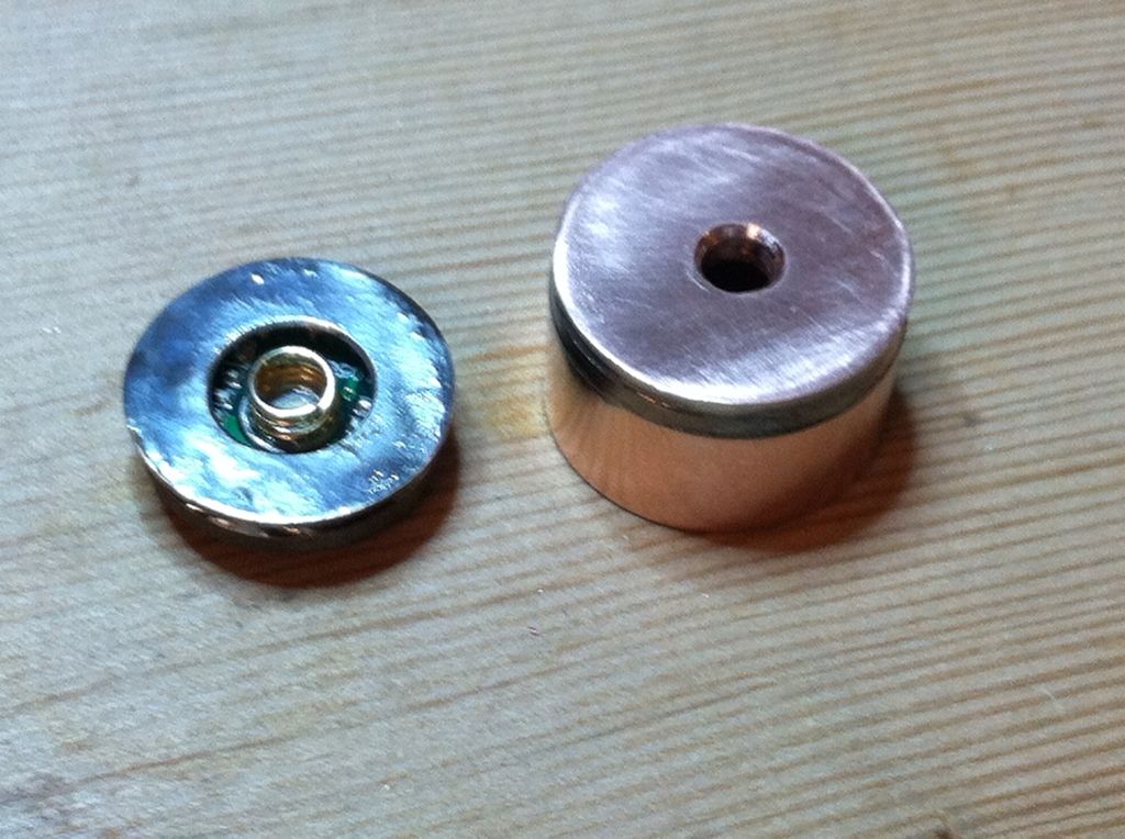
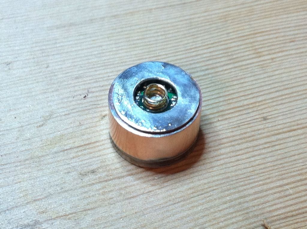
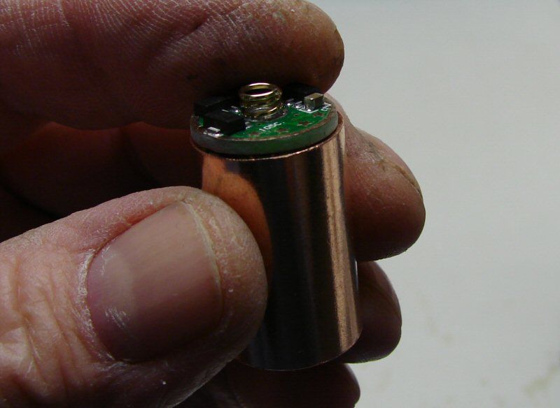
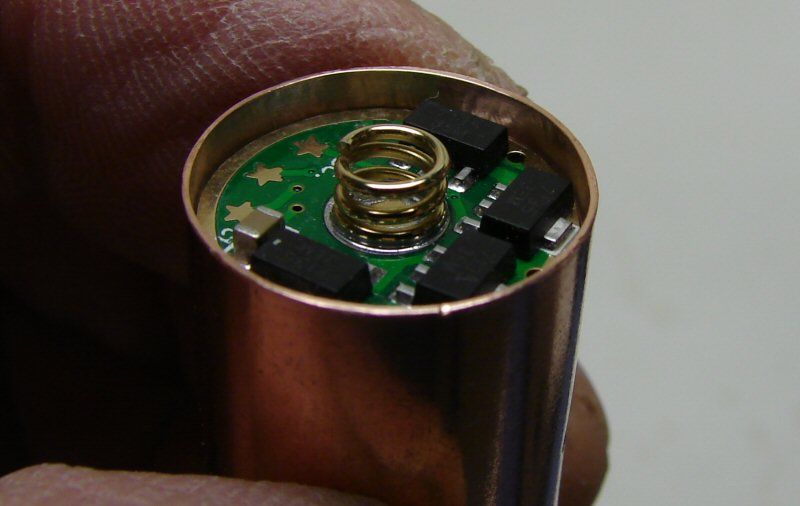
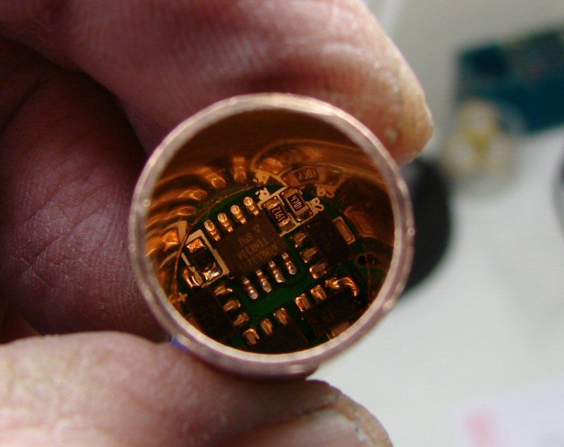
I am working on modifications to the pill/driver assembly, to make it more dependable and more rugged. After doing 3 or 4 of the driven lights, I can see weaknesses that need to be addressed. The updated pill/driver combo will go in all of these limited edition lights. I will have a sample of how they are done, once the sample light comes in. I will build it and show the photos of the guts. That's all for the moment. I will update when I have something to show.

EDIT: These lights do come with a dummy cell, for 14500 use and I am "guestimating" the lumens to be 350 lumens on high, 125 lumens on medium and 30 lumens on low. That is just a rough guess, but I think it will hold true and it gives something to think about for buyers. It is not a super bright light and max range (Not Maglite's bloated range), is about 40-50 yards.

02-17-13 UPDATED: Look at Post#8 for the NEw Pill Design. Never Mind, it's a FAIL.

02-18-2013 New Update: This will be a Nichia 219 High CRI light! The recent poll showed the Nichia winning at three to one odds and Craig just lowered the price, so it's a done deal. It will be the Nichia with a 1.4 amp or 1.5 amp driver.

Thanks O.L. PLEASE KEEP us informed, on this New Project

Everyone should OWN one of YOUR Creations.

I will try to,...

maybe if we could do a uk group buy ,it could lower the shipping costs.Dont really know just a suggestion.

the post office just raised prices again and eliminated parcel post too… definitely interested to see the sample light!

on a side note - have you ever thought of selling “drop-ins” for mini-mags? (I realize that stock hosts would require some modification)

Postal rates have gone up and International rates went up as well. It is making it very hard to do anything like this. I am concerned about it, but there is no real answer. If several people from one country went together and had them all shipped in one package, it would still be expensive. What happens when they arrive and have to be repacked and shipped out to the rest? There is not good answer. (except to move to China and ship from there).

Anyhow, all the prices are going up. Copper is getting too high to use and these may be some of the last lights using copper in them. So are other materials and shipping I pat, to get them, so all in all, it's quickly getting to where it is in no way "budget" any more.

I will amend the first post also, but These lights do come with a dummy cell, for 14500 use and I am "guesstimating" the lumens to be 350 lumens on high, 125 lumens on medium and 30 lumens on low. That is just a rough guess, but I think it will hold true and it gives something to think about for buyers. It is not a super bright light and max range (Not Maglite's bloated range), is about 40-50 yards.

Have you checked UPS or FedEx rates? I can’t say for certain, but I’d expect them to be less. I know UPS (at least used to) automatically insure up to $100 value.

At any rate, I’ll be in for one when you ask for commitment…

FedEx and UPS are higher in the US. I am not sure of international, but I will check. As far as insurance, USPS is strange about international. They automatically insure up to $400 on a package, but you can't file unless the package has been "Registered". Why not just add insurance and charge for it, I do not know. I am sure I will find something similar with FedEx and UPS.

The other problem I have is UPS & FedEx requirements of more than 2" padding around the object on all sides, in order for it to be legal and in order for it to be filed if it's damaged. That makes the packaging requirements soar! Imagine a foam block 8" by 6" by 6" and the cost of that, along with the box. I can't just send a packet, if it's by UPS or FedEx. They will not honor the claim. Been there and done that and they did not honor the claim. "not approved packaging" was their answer.

Yes, that means that All those packages sent by UPS and FedEx, with less than the minimum requirement would not be honored by the shipper. Instead companies just eat the loss and raise their prices to pad the loss. That is truly how it works. Lived in that world for years and years. The seller eats the cost, but I can't and won't.

FAIL

I thought I would do a little show and tell about the new pill. I decided to find a way to make the pill/led/TIR stronger and less difficult to produce. The old style leaves a lot to be desired and I just don't feel it is solid enough to withstand heavy use. So... I went about figuring out how to improve it and make it simpler and stronger.

Well, I think it's stronger, but I don't know about simpler. This idea of putting a driver into a 2AA maglite is really one of those situations where it makes more sense to just do DD. But... I know most everyone wants modes and I do too. What is sacrificed, is heat sink space. Less heat sinking to achieve the room for the driver. It's not a big pill in the first place, so every little bit counts, but it is a trade off and having medium and low modes, allows for longer run times and less overall heat. So the benefits out weight the negatives.

np1

The idea is to have a drop in for the LED version of the 2AA Maglite, using a NANJG driver, an XM-L and a TIR optic.

np2

What I usually do is to just use AA to glue the driver on the end and glue another post and plate over it, for the positive and ground. Too much gluing and not stable enough, besides the grounding isn't friendly or strong.

np3

So, I decided th go with a 1/2" copper coupling, that is bigger and bore out a place for the driver to sit into. It's opened up by holding it in the drill press and using an end mill bit to remove material. Not the best way, but a way that I can do. I went down 4mm into the coupling.

np4

The driver sits in tight and it's more than flush. I could have (and will) probably go about 3mm from now on. This is the test pill. I can now sit the driver in and actually solder the driver ring right to the coupling, by heating the coupling with my torch and dropping a little solder on the ring, till it melts and migrates to the coupling. Finally, a sturdy ground.

np5

There is one hitch. It's so tight in there, I may be shorting. I may have to coat the driver with AA, to isolate it at the edges, or possibly one of the Kapton tape rounds I have. I did not wire this one, since it's a test.

np7

I used a gold plated spring upside down and soldered it to the positive and then soldered a round on the spring for a contact. I also soldered a round onto the bottom of the coupling for the negative and drilled the hole to clear the spring. Now the bottom is much more rugged at the negative contact point and when someone tightens down hard, it won't fall apart, since it's soldered to the coupling, not just glued.

I will not be using copper for the negative and positive either. I am switching to Nickel Silver rounds. They will not tarnish so quickly as the copper and they are tougher also. I will not have to cut out positive rounds any more either, as I can now get 3/8" rounds for that. Saves a lot of time and sore fingers.

np8

Here's how the whole stack up looks like. The TIR optic comes down and touches the coupling. It happens to come out perfect. When the head is bored for the coupling and done so the coupling is flush with the top of the head, the TIR sticks up 3.5mm and the bezel tightens down to 3mm above the head, so it will tighten down on the TIR and hold it all in place, making a sturdy assembly and locked down tight.

The poor excuse for a drawing below, shows a little of how the pill is made. The heat sink is now Aluminum and fits in the coupling. The dimensions of a 1/2" coupling come out to where a 5/8" diameter Aluminum rod fits in well. No more copper shot and solder. Solid Aluminum will actually do better that all that solder inside. Much easier to deal with. I just order the pre-cut lengths and drill for the wires. Attach the LED with AA, solder the wires to the star, glue the TIR on top, slide it in and wire to the driver. Put the driver in and solder it to the coupling, add the spring and end cap. Ready to go!

np9

I'm sure I forgot to explain a step somewhere. I always do. Hard enough getting this far, so ask if it does not seem right.

Issues:

  • The springs need to be 14mm in length. I don't have any, so I had to stretch the one I had.
  • The 3/4" round is too big around for the copper coupling, so after soldering it on, I had to file it down to flush. The OD of the coupling is not a standard size for rounds or washers.

PARTS:

I now buy the Drivers, TIR optics, springs and LEDs from taobao. It takes a little longer, but the prices are better, especially in volume. Fasttech is also cheap, but they have messed up too many orders for me to use them any more.

UPDATE 02-17-13 IT'S A FAIL.

I finally tried to complete the pill. I made a heat sink and put the led on, wired it and slid it in. I got the driver soldered up to the led and put it in. Only problem is... I can't solder the driver ring to the copper coupling, nor the bottom round to the copper coupling. If I try to, all the solder runs off the wires for the led. Everything gets too hot too fast. I suspected that, but I was hopeful. It's a fail and I'm at the brick wall right now.

Very nice, thorough description. A couple things I might add are you can get copper repair coupling in 12” lengths that is cheaper than individual couplers and it’s easier to trim 1” from 12” than 1/4” from 1 1/4”. Also, you can pick up some extra room by trimming the battery tube/head threads in half and use a shorter spring.

You’ve definitely stepped up your pill production. :slight_smile:

Old,

I like the new pill. Take my thoughts as you will…
From what I understand, my main concern is that the twist switch relies on anodizing (head/body threads) to break contact with ground. The anodizing there should hold up well…nonetheless I’m thinking it will inevitably wear enough for contact to be made between the head and body.

My changes to the drawing are boxed in purple…

You could have the driver sit way deeper than the 2mm that my edited drawing suggests, even close to being flush as long as the (-) ring is insulated from the pill. I think with the sides of the pill supporting the driver with a fairly tight press fit, JB Weld or AA epoxy would be plenty to anchor the driver to the pill reliably. Scoring the inside of the pill would further enhance an epoxy’s grip, because a scored surface produces more surface area than just a smooth wall.

Also, I’d make sure that the (+) spring won’t short out on the (-) ring if it is compressed fully.

Like I said take my musings for what they are: musings!

I second this! Gives a little credit to the man living legend.

I like it ALL!!!! I like the logo. Danged nice write up and I really like the drawing of the pill !! I want one... don't care what they cost! We only live once or twice ...might as well have what we want!

Thanks Justin, great idea... AS USUAL!. I wish I had part of your creativity!!! Dan.

Very good point about the anodizing Slim. I had to fix that issue in my last Mini and will carry that isolation into future mods. By soldering wires from the ground ring to the negative contact ring I take the pill out of the circuit so ground does not come into contact with the head. Driver with negative ring on left and emitte side of pill on right.

Driver installed in pill.

With an o-ring or some Fujik to seat on in the head the ground ring becomes isolated.

@ Slim Pickins - I understand your thought about the isolation of the driver, to make the wear of the ano a non-player. I just don't see that it would be held in well enough. JB Weld conducts and AA is expensive, but it would work.

How would the bottom round be hooked onto the driver and how would ground be made? The reason I went this way is because I originally had the ground ring adhered to the driver (sandwich style like your drawing) and used a wire soldered between the two. Every light I made that way failed very quickly, due to flexing. Every time the body would come up against the ring, there would be a little flex, due to the fact that AA never really hardens, it is flexible and with a solder joint there can be no flex, or it will fatigue. If the four 7135 chips were places evenly around the driver, they would hold the contact ring from flexing, but they are situated to where some of the driver is bare and has no support for the bottom ring. That's where I thought AA would work, but it didn't.

Another thing is that AA turns to chalk after a long time of heat exposure. Might be months or longer, but it degrades from heat and these little lights get hotashell very quickly. I don't even link using AA between the star and heat sink, except that with this setup, it will all be under some pressure all the time, so it won't need but a super thin tacky film of AA to start with.

Anyhow, after 100% failure, I knew the setup had to be more robust, where it did not rely on any type of epoxy. If there's a way to isolate the driver from the pill and still make it to where there is no epoxy joints, then I would love to know how to do it.

I am not trying to shoot you down. I agree about the wear on the threads and that it could ruin the light some day. I agree about isolating the circuit, where that would not be an issue. I just don't know how to do that and still have a super solid pill where jamming the body against the contact ring will hold up and jamming it together is what will happen some of them for sure. Every time they are turned on.

Do you have any photos of how the driver is soldered to this ring? I can't tell from the photo. One of the real problems is my soldering skills with these drivers. I can solder copper all day, but I cannot get solder to stick to these outer rings or to the wire contacts. I think my poor soldering skills also part of the reason for the failed method I was using. The way I have tried now, eliminates that, since it's direct to the copper coupling and I can solder that. My soldering skills are not going to get any better. I reach a point of frustration where I just seek another way, because I don't have the patience or desire to try any more. LOL It's called miserable old man syndrome.

You might want to check that again… mine doesn’t.

+1, just tested a random chunk of it I had lying around and no connection.

I use a small dab of Artic Silver thermal epoxy on top of each chip. A wire is soldered into each of the ground ring holes and drilled and soldered through the ground disc. The void between the disc and the driver is filled with Fujik which seems to tolerate the heat well. We are the R&D for this mod and each one I do has tweaks to share. I have noticed the anodizing on the black units is much more robust and resistant to wear than any of the other choices. For a collectors item thie new OL version should be okay but for edc use some form of isolation would be better. Maybe the use of the 101AK board(with it’s integral ground ring) and stacking chips to avoid the extra wires and ground disc is a better option. I made one XML drop that way and the above drop in with 3x Nichia both with 7 chips on the driver. I use them interchangeably in the same host and will let everyone know which fails first. To be honest, I would prefer a 1.4A Nichia to a 3A XML in the limited edition light. You do that so often it’s almost as much a signature as the AA Mag itself.

I have fried drivers using JB weld as a potting compound. Maybe it was my poor method, not the JB weld.Frown