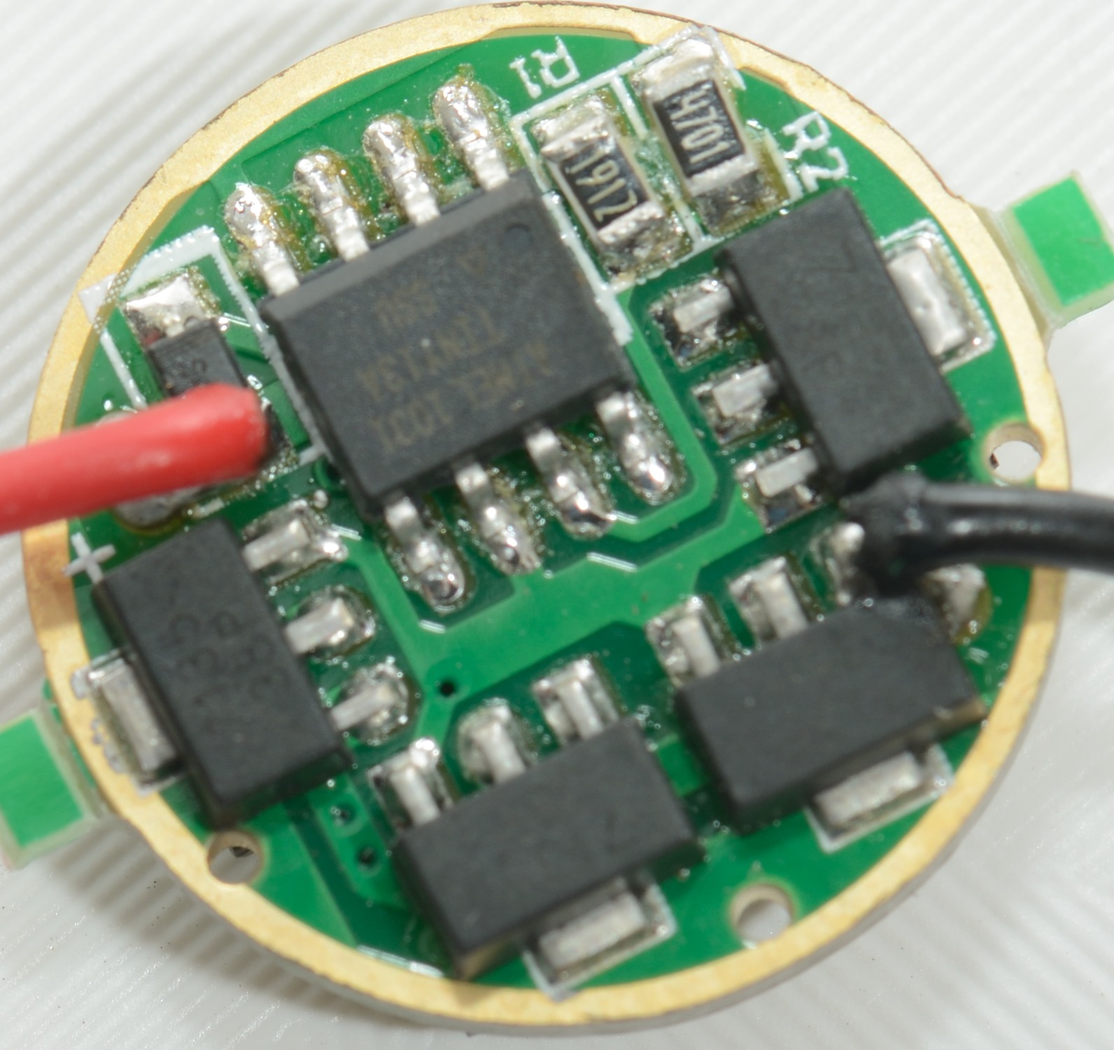
Am I correct in saying that with the Qlite driver shown in the picture, the negative lead and the adjacent 7135 chip end pin are bridged with solder?
When I desolder the negative lead I cannot be certain that the bridge is the result of melting the solder or was it already like that, the thing is so small and when the negative lead is attached during manufacture it’s right in the way and I cannot see any potential solder bridge that’s already there.
Also, the positive lead. Does the track on the board from the positive pad then go to the D1 diode? I’m assuming it does as some photo’s shown them bridged together with solder.
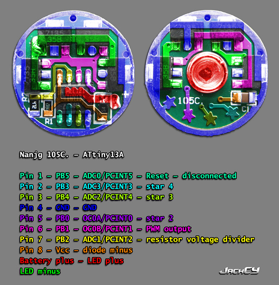
That’s great, that definitely shows the positive lead and the connection to the diode.
Just the negative lead now, it does look like it’s okay to bridge to the 7135 chip. I’ll see if I can remove all of the solder from the negative pad and then check it with the multimeter.