To simplify, 1D thermal resistance is a function of conductivity, layer thickness and conducting X-section area. If we’re stuck with using dielectric and copper, we can control 2 of those three variables.
Mitigate thermal bottlenecking by designing positive/negative copper pads as thick and wide as possible, instead of narrow traces. Heat flux can flow through larger cross section of dielectric layer.
Bottom layer is copper and thinner than than +/- pad layer.
For given dielectric layer thickness,
Larger X-section of dielectric -> smaller thermal resistance of dielectric layer -> smaller ∆Temperature across dielectric layer -> cooler temp @ LED die. It won’t ever be as good as true DTP but depending on PCB size it could approach DTP performance. Also, if it works well with 16mm board it will only do better at 20mm.
Deleting a just published post causes the forum thread answer notification to fail. Thus, if you need to change your just published post, edit it. Thanks.
Please avoid fully quoting lenghty posts, namely with nested quotes. Trim quotes down to the essential. Helps with neatness and legibility. Thanks.
BeO has safety risks but a similar safer ceramic might suffice. I’m guessing this is a cheaper-easier way for Nichia to reach their efficiency goals within their stated usage parameters. That would be a good business move for an emitter manufacturer, but maybe not for us flashlight people.
It is well to remember that we’re just riding along with the emitter manufacturers- we are not driving the bus. If the emitter business slows due to market saturation or whatever maybe they’ll spend some time designing things just for us. Until then bursts of brilliance followed by dim blue haze (sometimes followed by blue air) will be our baliwick and bane but it shall not stop our relentless pursuit of more and purer lumens! Onward and forward! Full speed ahead!
FastTech blows goats for half price, once again my order got delayed 12½ days later, they don't seem to be able to get a hold of these alu-nano plates. I'm on the verge of ordering a Sinkpad and be done with it.
Cheers
P.S.: edited that not so discreet smiley.
—
Deleting a just published post causes the forum thread answer notification to fail. Thus, if you need to change your just published post, edit it. Thanks.
Please avoid fully quoting lenghty posts, namely with nested quotes. Trim quotes down to the essential. Helps with neatness and legibility. Thanks.
Here’s where I get a little confused with electrical arrangements in LEDs.
A common 5.6mm laser diode-can, can be powered over the ground pin, which is sometimes (-) and sometimes (+). As an example, 405nm diodes use a boost driver, 18650 for power, and the body would be negative just like a flashlight, with a diode vF of 5-6V. OK, it’s common practice to solder the negative and ground pin together on the same wire, positive pin on other wire of course. Clearly the driver still has to complete the circuit for power to flow. Why can’t an LED resolve the same outcome? Where negative could be your DTP.
Anyways, I would certainly love to try these two LEDs. It’s incredible what the 219C is rated at on the spec sheet (326 lumens, I think), vs what it can actually output. Just think about the possibility of the other two then, when cooled correctly. The 144AM rated at 1300-1400 lumens at highest bin; I could only imagine a single mono die LED with moderate CRI potentially unleashing 3200-4000 lumens under a smooth reflector.
A little more 144A info:
- Emitting area: 4×4mm (16mm2) – same configuration as a XHP35 (with lower forward voltage)?
- Aluminium Nitride substrate (285 W/(m·K))
- Gold contacts
Quote:
Distributor of the brand Nichia in Italy, Welt Electronic presents the new multichip series 144A. Nichia, a company of the first
magnitude in the products Mid Power and High Power, deals with the application market outdoor, street and tunnel lighting,
with a multichip Super Hight Power consists of four chips of 2 mm2, close to each other and arranged in a square: a plus optically unequaled.
These are the characteristics of the series 144A: Aluminium Nitride substrate, a component that increases the efficiency and
lowers the thermal resistance; Nichia Flip – Chip technology, which eliminates the process of wire bonding as a connection between the anode and cathode, presents a critical element in less than the technologies adopted by
other manufacturers; gold electrodes, which allow not to decay in application, because it is completely free from corrosion in an
environment saturated
Alumininium nitrite looks like the way to go creating a board for mounting these.. it should be reasonably cheap to have someone make a bunch of 16 and 20mm disks… then glue two pieces of copper sheet to the top to act as electrodes. Done.
Welt Electronics sounds like one possible source.
That’s more like an XHP70 actually (which has 2mm² “XM-L2” dies), yet made as a monolithic die of course without the spaces.
That would be good! XHP70-like output, no window frame=no donut hole.
If we’re talking about what-ifs, this company is placing Cree dies into cylindrical LASER style cans! (I can find the company again if anyone actually wants to know who.)
Of course I would still love to know the reason why negative could not be body-grounded for heatsinking if positive was isolated.
A thermal pad is needed because you want to thermally connect the led to the flashlight with no non-metal obstructions, and the electrical pads can not be used for a direct metal connection. The output advantage of a direct thermal path only starts at an out-of-spec current (under 3A a XM-L2 shows hardly an advantage) and gets more when current increases. What would work really well as a non-DTP board would be a non-DTP board like this: !https://farm2.staticflickr.com/1666/25785416473_72a29f05fd_m.jpg! 
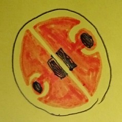
(orange is the copper-poor, blue is the exposed copper for soldering) If the MCPCB is made with an as thick copper-poor as can be produced, the heat will spread sideways fast and have then enough surface area to cross the dielectric layer efficiently. This board can be used with all the two-pad leds that are out there and boost their performance compared to the common boards. No-one makes these, perhaps we can ask Hank to have a Noctigon version of this board designed.
Already made several MCPCB specially designed for this one! You can crash test the LEDs and the MCPCB (I got several CCTs) after Maukka spectral tested them all
The samples took off the factory in Japan in 160829. Don't know how long until they get here.
I created a thread HERE (copied from my thread in CPF), because I didn't know you did it first Worth take a look for some comparison with popular CRI90 Crees. Well, at least spec by spec in the high 90CRI domain, it's superior than comparable XHP50 (colour and performance).
Of course I would still love to know the reason why negative could not be body-grounded for heatsinking if positive was isolated. :-)
Most, if not all, flashlight led drivers regulate the current to the led by the low side. This means the led's positive lead is directly connected to the battery anode, and its negative lead goes down to the driver, while at the same time the flashlight body, and thus the led's thermal pad, is at battery cathode potential.
And this is the solution, for y'all to see:
Installing the batteries in reverse, we would set the thermal pad and the led's positive lead at anode potential: both leads can get unified. In this way, we would only need to isolate the led's negative lead to the driver. However, this requires a slight led driver PCB redesign to shift their boards polarities: battery cathode connected from the underside central pad, anode through the driver sides/pill and, well, through a positive wire coming from the led MCPCB (lower resistance connection, fellows).
Did I put my foot on someone's mouth? Where's my prize?
Cheers
—
Deleting a just published post causes the forum thread answer notification to fail. Thus, if you need to change your just published post, edit it. Thanks.
Please avoid fully quoting lenghty posts, namely with nested quotes. Trim quotes down to the essential. Helps with neatness and legibility. Thanks.
We would have to know if both pads are doing the heat transfer to the star.
if so, one could solder the LED on 2 half circles of copper and then put electrical isolation between it and the pill.
That way you have direct thermal path to the star and a big surface with maybe kapton film and some goo on the star.
This way you can avoid the fuss of re-designing the host flashlight.
.
[EDIT]
Just learned that 90% of the heat transfer is through the cathode.
But i think it’s a good option to isolate the star from the pill, not the LED from the star.
[/EDIT]
BLF Member djozz has some very nice non-DTP boards for the Nichias without thermal pads. He had some made so he could test out his design with a new MCPCB manufacturer that showed up here a while back. He’s selling them now, at cost. They’re $2USD each. Look at his signature line for a link to the thread.
—
The Cycle of Goodness: “No one prospers without rendering benefit to others”
- The YKK Philosophy
BLF Member djozz has some very nice non-DTP boards for the Nichias without thermal pads. He had some made so he could test out his design with a new MCPCB manufacturer that showed up here a while back. He’s selling them now, at cost. They’re $2USD each. Look at his signature line for a link to the thread.
I think that clemence’s board, that has direct connection to the core on the cathode side, should perform better than my boards, but of course when these leds arrive I will do an attempt to test these boards directly against each other with the same led.
Hmmmm, I think I have to send Maukka one extra NV4 for you to test. I have several 6V NV4 @ 6500K; R7000; D1200 rank, that I’m not interested at all. A perfect guinea pig for the dead match.
We would have to know if both pads are doing the heat transfer to the star.
if so, one could solder the LED on 2 half circles of copper and then put electrical isolation between it and the pill.
That way you have direct thermal path to the star and a big surface with maybe kapton film and some goo on the star.
This way you can avoid the fuss of re-designing the host flashlight.
.
[EDIT]
Just learned that 90% of the heat transfer is through the cathode.
But i think it’s a good option to isolate the star from the pill, not the LED from the star.
[/EDIT]
Long before electrically neutral thermal pad introduced, all LED designed that way. Miniaturization and higher LED wattage has change the norms. But when space is not the limitation, non thermal pad LED and non DTP board usually cheaper to produce.
BLF Member djozz has some very nice non-DTP boards for the Nichias without thermal pads. He had some made so he could test out his design with a new MCPCB manufacturer that showed up here a while back. He’s selling them now, at cost. They’re $2USD each. Look at his signature line for a link to the thread.
I think that clemence’s board, that has direct connection to the core on the cathode side, should perform better than my boards, but of course when these leds arrive I will do an attempt to test these boards directly against each other with the same led.
Well, I don’t know what his design looks like, but I was thinking that electrically connecting the LED- to the board makes the whole thing useless for 99.99% of flashlights, because the driver regulates current on the negative side. Then ‘grounding’ the negative side of the LED makes the light single mode Turbo only!
—
The Cycle of Goodness: “No one prospers without rendering benefit to others”
- The YKK Philosophy
BLF Member djozz has some very nice non-DTP boards for the Nichias without thermal pads. He had some made so he could test out his design with a new MCPCB manufacturer that showed up here a while back. He’s selling them now, at cost. They’re $2USD each. Look at his signature line for a link to the thread.
I think that clemence’s board, that has direct connection to the core on the cathode side, should perform better than my boards, but of course when these leds arrive I will do an attempt to test these boards directly against each other with the same led.
Well, I don’t know what his design looks like, but I was thinking that electrically connecting the LED- to the board makes the whole thing useless for 99.99% of flashlights, because the driver regulates current on the negative side. Then ‘grounding’ the negative side of the LED makes the light single mode Turbo only!
…so we should electrically insulate / isolate the MCPCB from the pill with a thin layer of something plus some thermal goo.
Should i make a crude drawing?
The current sense feedback is on the negative side of buck/boost drivers, to my knowledge. This is baaaad news. For the love of g0d, why have those @#$%ns chosen the cathode slug as the main heat sewage? They just weren't thinking in flashlights at all, which I can understand, but it could also have implications for “integrated” drivers.
Of course, just an opinion. Time for BeO/diamond dielectric MCPCB's fellows.
Cheers
—
Deleting a just published post causes the forum thread answer notification to fail. Thus, if you need to change your just published post, edit it. Thanks.
Please avoid fully quoting lenghty posts, namely with nested quotes. Trim quotes down to the essential. Helps with neatness and legibility. Thanks.
My MCPCB is designed for prototyping purpose. It will accommodate various optics and mounts – that’s why it’s big and thick without pre drilled holes. The design makes it easy for various testing, I can mill it down to circular 20mm or any shapes without risk to short any electrical traces because it’s shorted anyway.
To make it electrically neutral is EASY. You just put any commercially available dielectric tape/epoxy/glue between the MCPCB and the host. The heat concentration already spread to area 95 times the cathode size, less delta T. Even if we use dielectric material with only 3W/m.K (thin layer of course) thermal conductivity would still theoritically superior than those LED with thermal pad. The cathode makes metal – metal contact through copper and solder connection, less thermal resistance than through dielectric – solder connection from the LED thermal pad base. Unless the base of those LED with thermal pad is made from material with thermal conductivity superior than copper this design would be better for high power LED. But I can’t be really sure until mr Djozz done with his back to back test.
The best test is to compare it to XHP50 with equal sized DTP board.
The package is on the way to Maukka, should be there in a week. I added extra bare NV4 emitters from each type for you. There are total 13 emitters including 3 pcs NVSL219CT R9050.
PACKINGLIST
——————
1. NV4W144AME (6V) – sm653E1200KR70 – 1 pc
2. NV4W144ARE (12V) – sm575E1000Lv9R9050 – 1 pc
3. NV4W144AME (6V) – sm575E1000KR9050 – 1 pc
4. NV4L144ARE (12V) – sm305E900Lv9R9050 – 1 pc
5. NV4L144AME (6V) – sm305E1100KR8000 – 1 pc
6. NV4W144AME (6V) – sm653E1200KR70
soldered on VirEnce DTPMCPCB – 1 pc
7. NV4W144ARE (12V) – sm575E1000Lv9R9050
soldered on VirEnce DTPMCPCB – 1 pc
8. NV4W144AME (6V) – sm575E1000KR9050
soldered on VirEnce DTPMCPCB – 1 pc
9. NV4L144ARE (12V) – sm305E900Lv9R9050
soldered on VirEnce DTPMCPCB – 1 pc
10. NV4L144AME (6V) – sm305E1100KR8000table(table#posts).
soldered on VirEnce DTPMCPCB – 1 pc
Thats a lot of work to test^ but can’t wait to see them!
Correct, given that emitter testing the way I do it (no automation whatsoever, which is labor intensive but also adds to the accuracy) takes several hours, and that I have a job and a family, I’m sure that I do not have the time to test all 13. But I will pick the emitters that will tell enough about the others that a complete picture can be derived.
I wish I live closer so I can bring the beers and coffee. Yes, I just need them all spectra tested by Maukka. Djozz only need to crash test any LED of his choice. As my/our gratitude to them, they can share the pre production Nichias (if Djozz haven’t kill them already …. )
We’re just gonna have to put due diligence to work, aren’t we? Build em, work em hard, see what shakes loose…
To simplify, 1D thermal resistance is a function of conductivity, layer thickness and conducting X-section area. If we’re stuck with using dielectric and copper, we can control 2 of those three variables.
Mitigate thermal bottlenecking by designing positive/negative copper pads as thick and wide as possible, instead of narrow traces. Heat flux can flow through larger cross section of dielectric layer.
Bottom layer is copper and thinner than than +/- pad layer.
For given dielectric layer thickness,
Larger X-section of dielectric -> smaller thermal resistance of dielectric layer -> smaller ∆Temperature across dielectric layer -> cooler temp @ LED die. It won’t ever be as good as true DTP but depending on PCB size it could approach DTP performance. Also, if it works well with 16mm board it will only do better at 20mm.
Beryllium Oxide (Wikipedia)
Cheers
Deleting a just published post causes the forum thread answer notification to fail. Thus, if you need to change your just published post, edit it. Thanks.
Please avoid fully quoting lenghty posts, namely with nested quotes. Trim quotes down to the essential. Helps with neatness and legibility. Thanks.
- Yeah, but is it ultra high CRI?

BeO has safety risks but a similar safer ceramic might suffice. I’m guessing this is a cheaper-easier way for Nichia to reach their efficiency goals within their stated usage parameters. That would be a good business move for an emitter manufacturer, but maybe not for us flashlight people.
It is well to remember that we’re just riding along with the emitter manufacturers- we are not driving the bus. If the emitter business slows due to market saturation or whatever maybe they’ll spend some time designing things just for us. Until then bursts of brilliance followed by dim blue haze (sometimes followed by blue air) will be our baliwick and bane but it shall not stop our relentless pursuit of more and purer lumens! Onward and forward! Full speed ahead!
Phil
Might be an instance where the nano materials dielectric would be useful combined with max sized +/- traces.
Three Tanna leaves to give him life, nine to give him movement. But what if he eats the whole bag?
Scott
Nano-what?
FastTech blows goats for half price, once again my order got delayed 12½ days later, they don't seem to be able to get a hold of these alu-nano plates. I'm on the verge of ordering a Sinkpad and be done with it.
Cheers
P.S.: edited that not so discreet smiley.
Deleting a just published post causes the forum thread answer notification to fail. Thus, if you need to change your just published post, edit it. Thanks.
Please avoid fully quoting lenghty posts, namely with nested quotes. Trim quotes down to the essential. Helps with neatness and legibility. Thanks.
- Yeah, but is it ultra high CRI?

Barkuti, pretty sure an animated smiley flippin the bird is in direct violation of forum rules on profanity. You might wanna check that…
Here’s where I get a little confused with electrical arrangements in LEDs.
A common 5.6mm laser diode-can, can be powered over the ground pin, which is sometimes (-) and sometimes (+). As an example, 405nm diodes use a boost driver, 18650 for power, and the body would be negative just like a flashlight, with a diode vF of 5-6V. OK, it’s common practice to solder the negative and ground pin together on the same wire, positive pin on other wire of course. Clearly the driver still has to complete the circuit for power to flow. Why can’t an LED resolve the same outcome? Where negative could be your DTP.
Anyways, I would certainly love to try these two LEDs. It’s incredible what the 219C is rated at on the spec sheet (326 lumens, I think), vs what it can actually output. Just think about the possibility of the other two then, when cooled correctly. The 144AM rated at 1300-1400 lumens at highest bin; I could only imagine a single mono die LED with moderate CRI potentially unleashing 3200-4000 lumens under a smooth reflector.
I like bright lights, and I cannot lie.
In the meantime, are they seen for sale anywhere? I would not mind doing an output test on a home-made copper board, like I did for the Luxeon Z test.
link to djozz tests
A little more 144A info:
- Emitting area: 4×4mm (16mm2) – same configuration as a XHP35 (with lower forward voltage)?
- Aluminium Nitride substrate (285 W/(m·K))
- Gold contacts
Alumininium nitrite looks like the way to go creating a board for mounting these.. it should be reasonably cheap to have someone make a bunch of 16 and 20mm disks… then glue two pieces of copper sheet to the top to act as electrodes. Done.
Welt Electronics sounds like one possible source.
That’s more like an XHP70 actually (which has 2mm² “XM-L2” dies), yet made as a monolithic die of course without the spaces.
That would be good! XHP70-like output, no window frame=no donut hole.
If we’re talking about what-ifs, this company is placing Cree dies into cylindrical LASER style cans! (I can find the company again if anyone actually wants to know who.)
Of course I would still love to know the reason why negative could not be body-grounded for heatsinking if positive was isolated.
I like bright lights, and I cannot lie.
Already made several MCPCB specially designed for this one! You can crash test the LEDs and the MCPCB (I got several CCTs) after Maukka spectral tested them all
The samples took off the factory in Japan in 160829. Don't know how long until they get here.
I created a thread HERE (copied from my thread in CPF), because I didn't know you did it first
Worth take a look for some comparison with popular CRI90 Crees. Well, at least spec by spec in the high 90CRI domain, it's superior than comparable XHP50 (colour and performance).
Cheers,
Clemence
www.virence.com
Physical and thermal properties of solder alloy - Shooting Beamshots With HDR - Nichia E21A Tint Shots
Its Okay To Be Smart - SmarterEveryDay - Deep Look - Veritasium - Tech Ingredients
Most, if not all, flashlight led drivers regulate the current to the led by the low side. This means the led's positive lead is directly connected to the battery anode, and its negative lead goes down to the driver, while at the same time the flashlight body, and thus the led's thermal pad, is at battery cathode potential.
And this is the solution, for y'all to see:
Installing the batteries in reverse, we would set the thermal pad and the led's positive lead at anode potential: both leads can get unified. In this way, we would only need to isolate the led's negative lead to the driver. However, this requires a slight led driver PCB redesign to shift their boards polarities: battery cathode connected from the underside central pad, anode through the driver sides/pill and, well, through a positive wire coming from the led MCPCB (lower resistance connection, fellows).
Did I put my foot on someone's mouth? Where's my prize?
Cheers
Deleting a just published post causes the forum thread answer notification to fail. Thus, if you need to change your just published post, edit it. Thanks.
Please avoid fully quoting lenghty posts, namely with nested quotes. Trim quotes down to the essential. Helps with neatness and legibility. Thanks.
- Yeah, but is it ultra high CRI?

We would have to know if both pads are doing the heat transfer to the star.
if so, one could solder the LED on 2 half circles of copper and then put electrical isolation between it and the pill.
That way you have direct thermal path to the star and a big surface with maybe kapton film and some goo on the star.
This way you can avoid the fuss of re-designing the host flashlight.
.
[EDIT]
Just learned that 90% of the heat transfer is through the cathode.
But i think it’s a good option to isolate the star from the pill, not the LED from the star.
[/EDIT]
Most of the heat generated at the cathode side. I made my design according to Nichia’s suggestion: Here
www.virence.com
Physical and thermal properties of solder alloy - Shooting Beamshots With HDR - Nichia E21A Tint Shots
Its Okay To Be Smart - SmarterEveryDay - Deep Look - Veritasium - Tech Ingredients
BLF Member djozz has some very nice non-DTP boards for the Nichias without thermal pads. He had some made so he could test out his design with a new MCPCB manufacturer that showed up here a while back. He’s selling them now, at cost. They’re $2USD each. Look at his signature line for a link to the thread.
The Cycle of Goodness: “No one prospers without rendering benefit to others”
- The YKK Philosophy
I think that clemence’s board, that has direct connection to the core on the cathode side, should perform better than my boards, but of course when these leds arrive I will do an attempt to test these boards directly against each other with the same led.
link to djozz tests
Hmmmm, I think I have to send Maukka one extra NV4 for you to test. I have several 6V NV4 @ 6500K; R7000; D1200 rank, that I’m not interested at all. A perfect guinea pig for the dead match.
www.virence.com
Physical and thermal properties of solder alloy - Shooting Beamshots With HDR - Nichia E21A Tint Shots
Its Okay To Be Smart - SmarterEveryDay - Deep Look - Veritasium - Tech Ingredients
Long before electrically neutral thermal pad introduced, all LED designed that way. Miniaturization and higher LED wattage has change the norms. But when space is not the limitation, non thermal pad LED and non DTP board usually cheaper to produce.
www.virence.com
Physical and thermal properties of solder alloy - Shooting Beamshots With HDR - Nichia E21A Tint Shots
Its Okay To Be Smart - SmarterEveryDay - Deep Look - Veritasium - Tech Ingredients
Well, I don’t know what his design looks like, but I was thinking that electrically connecting the LED- to the board makes the whole thing useless for 99.99% of flashlights, because the driver regulates current on the negative side. Then ‘grounding’ the negative side of the LED makes the light single mode Turbo only!
The Cycle of Goodness: “No one prospers without rendering benefit to others”
- The YKK Philosophy
Should i make a crude drawing?
The current sense feedback is on the negative side of buck/boost drivers, to my knowledge. This is baaaad news. For the love of g0d, why have those @#$%ns chosen the cathode slug as the main heat sewage? They just weren't thinking in flashlights at all, which I can understand, but it could also have implications for “integrated” drivers.
Of course, just an opinion. Time for BeO/diamond dielectric MCPCB's fellows.
Cheers
Deleting a just published post causes the forum thread answer notification to fail. Thus, if you need to change your just published post, edit it. Thanks.
Please avoid fully quoting lenghty posts, namely with nested quotes. Trim quotes down to the essential. Helps with neatness and legibility. Thanks.
- Yeah, but is it ultra high CRI?

My MCPCB is designed for prototyping purpose. It will accommodate various optics and mounts – that’s why it’s big and thick without pre drilled holes. The design makes it easy for various testing, I can mill it down to circular 20mm or any shapes without risk to short any electrical traces because it’s shorted anyway.
To make it electrically neutral is EASY. You just put any commercially available dielectric tape/epoxy/glue between the MCPCB and the host. The heat concentration already spread to area 95 times the cathode size, less delta T. Even if we use dielectric material with only 3W/m.K (thin layer of course) thermal conductivity would still theoritically superior than those LED with thermal pad. The cathode makes metal – metal contact through copper and solder connection, less thermal resistance than through dielectric – solder connection from the LED thermal pad base. Unless the base of those LED with thermal pad is made from material with thermal conductivity superior than copper this design would be better for high power LED. But I can’t be really sure until mr Djozz done with his back to back test.
The best test is to compare it to XHP50 with equal sized DTP board.
www.virence.com
Physical and thermal properties of solder alloy - Shooting Beamshots With HDR - Nichia E21A Tint Shots
Its Okay To Be Smart - SmarterEveryDay - Deep Look - Veritasium - Tech Ingredients
I can add the XHP50 test to the graph for comparison
link to djozz tests
The package is on the way to Maukka, should be there in a week. I added extra bare NV4 emitters from each type for you. There are total 13 emitters including 3 pcs NVSL219CT R9050.
PACKING LIST
——————
1. NV4W144AME (6V) – sm653E1200KR70 – 1 pc
2. NV4W144ARE (12V) – sm575E1000Lv9R9050 – 1 pc
3. NV4W144AME (6V) – sm575E1000KR9050 – 1 pc
4. NV4L144ARE (12V) – sm305E900Lv9R9050 – 1 pc
5. NV4L144AME (6V) – sm305E1100KR8000 – 1 pc
6. NV4W144AME (6V) – sm653E1200KR70
soldered on VirEnce DTP MCPCB – 1 pc
7. NV4W144ARE (12V) – sm575E1000Lv9R9050
soldered on VirEnce DTP MCPCB – 1 pc
8. NV4W144AME (6V) – sm575E1000KR9050
soldered on VirEnce DTP MCPCB – 1 pc
9. NV4L144ARE (12V) – sm305E900Lv9R9050
soldered on VirEnce DTP MCPCB – 1 pc
10. NV4L144AME (6V) – sm305E1100KR8000table(table#posts).
soldered on VirEnce DTP MCPCB – 1 pc
11. NVSL219CT – sm305D200L1R9050
soldered on SinkPad DTP MCPCB – 3 pcs
TOTAL: 13 ITEMS
www.virence.com
Physical and thermal properties of solder alloy - Shooting Beamshots With HDR - Nichia E21A Tint Shots
Its Okay To Be Smart - SmarterEveryDay - Deep Look - Veritasium - Tech Ingredients
Thats a lot of work to test^ but can’t wait to see them!
Texas Avenger Driver Series
My LED Test series - XP-L2 V5 - Nichia 219C 90+ CRI - Latticebright "XM-L" - XHP35 & PWM efficiency - XHP50 - XP-L V5 - XM-L2 U2 - XP-G3 S5 - XP-L HI V2 - Oslon Square & direct comparison to Djozz tests - Nichia 319A - Nichia 219B 9080 CRI - Nichia 219C D320 - Nichia 229AT - XHP70.2 P2 - XHP50.2 J4 - Samsung LH351D
Easy comparison tool for all my LED tests
Correct, given that emitter testing the way I do it (no automation whatsoever, which is labor intensive but also adds to the accuracy) takes several hours, and that I have a job and a family, I’m sure that I do not have the time to test all 13. But I will pick the emitters that will tell enough about the others that a complete picture can be derived.
link to djozz tests
I wish I live closer so I can bring the beers and coffee. Yes, I just need them all spectra tested by Maukka. Djozz only need to crash test any LED of his choice. As my/our gratitude to them, they can share the pre production Nichias (if Djozz haven’t kill them already ….
)
www.virence.com
Physical and thermal properties of solder alloy - Shooting Beamshots With HDR - Nichia E21A Tint Shots
Its Okay To Be Smart - SmarterEveryDay - Deep Look - Veritasium - Tech Ingredients
Nichia’s are tough leds, hard to kill, but I will give killing a go for at least one, my PS goes up to 20A if needed
link to djozz tests
www.virence.com
Physical and thermal properties of solder alloy - Shooting Beamshots With HDR - Nichia E21A Tint Shots
Its Okay To Be Smart - SmarterEveryDay - Deep Look - Veritasium - Tech Ingredients
Pages