Gords1001 and I have received 8.4v versions of the newly popular 4A ramping driver from I-O. This is a mixup from the distributor I'd imagine and some were accidentally shipped out by accident to buyers of the 4.2v version. I checked with Hank to see if mine were the correct or incorrect versions. Turns out the last 2 I bought ended up being the 8.4v versions. Here is how you can tell which version you have.
Here's the official scoop from Hank which I confirmed on the ones I just got (8.4v BTW)...
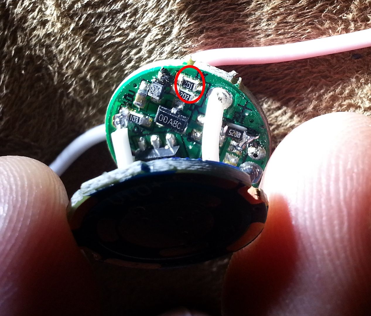
You will notice in the pic that one of the resistors is circled. If yours says "101" on it then you have the 4.2v single cell version. If, like in my pic, yours says "102" then you have the 8.4v double cell version of the driver.
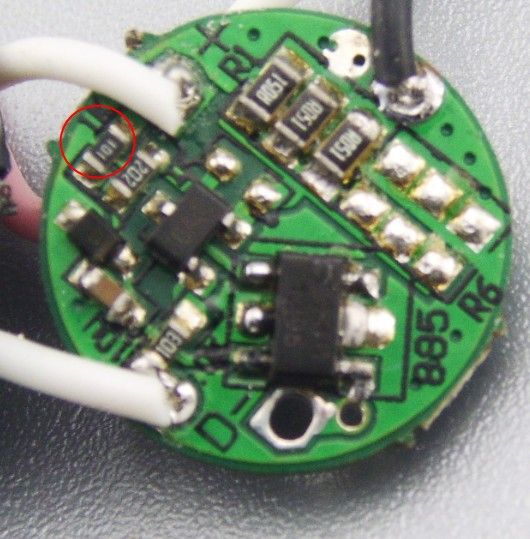
The color of the leads has no bearing on which version you might have. Here is a pic from Hank showing the 4.2v version with the "101" chip...
I’m not sure if this will work, but on AK-47A boards I measured about 4MOhm of resistance across the LED output (tested on two units). This may vary based on the meter used, but if everything else is kept the same, maybe you can get a hint at which is which… unless you tied the outputs together before potting.
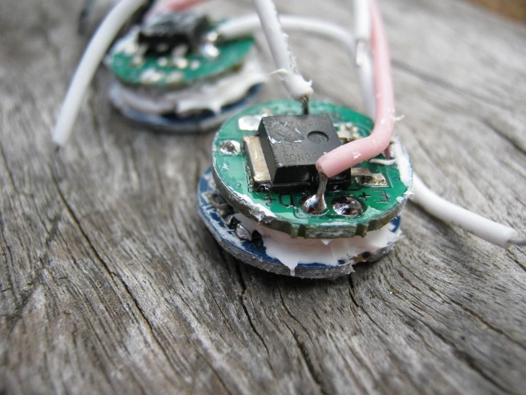
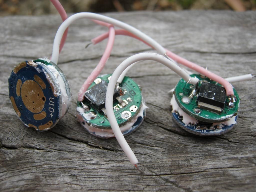
Looks like mine are all 8.4 and then an odd one that doesnt look like either:
I have two that look like this:
But then one that looks like this:
All should have been 4.2 versions. -
First, thanks!! I would have never been able to tell if you hadnt started this thread. thanks for that.
Second, I guess I just email I-O and go from there? Hopefully they dont expect me to return these.
Third: What is the driver with the white spacer?
As in another thread, we noticed the fishy pink wires. I was suspect that the Specs were different, thanks for doing the research. I was relutant to do a build until I found out, good thing you were on the ball on this one. Kind of disconcerting, when one goes to the effort to do a build…Thanks again for alerting us to this, and doing the ground work, kudos…
That white ‘spacer’ isn’t a spacer. It’s just the 202 Resistor on upside down. Doesn’t affect operation at all.
P.S. the way to read resistor codes like that…
202 = 20 Plus 2 Extra Zeros. = 2000 Ohms = 2K Ohms.
101 = 10 Plus 1 Extra Zero. = 100 Ohms.
102 = 10 Plus 2 Extra Zeros = 1000 Ohms = 1K Ohms.
The problem is, on mine, the excellent UI is not there, is pretty much unusable tbh. And on two cells I read 4.89a at the tailcap, not really xm-l friendly. Bummer, I’d be very very very happy if on two cells I had the same UI as previous and 4a to the emitter. I’d be begging hank for more of them.
I thought that when you used two cells and measured the tailcap current that you basically just double the amps and that is what is going to the emitter? That would mean that there is nearly 10a at the emitter?
No, that’s the point, if you double the amps as a ball park figure…9.78a.
Good job the damm thing won’t stop ramping, but it ramps twice, goes out, then you have to start again. I’ve probably knocked 5000hrs off the life of that poor tortured t5 lol, pretty bright for a nw emitter….
Edited my crap maths, six cans of decent beer is taking its toll. :bigsmile:
well, to get 4A to the LED with two cells I’d assume you’d need LESS current from the battery than with the 1 cell driver. Assume Vf of LED is 3.20V. Power at LED is 3.2x4=12.8W. Assuming an efficiency of 90% would put input power in the range of 12.8/.9= 14.22W. With a battery voltage of lets say 4.0Vx2=8V, input current should be in the range of 14.2/8= 1,77A… Hank did say that there are two versions, ONE with ramping mode and the OTHER with H, M, L only. How do you guys know that it’s designed for 8.4V?
What current draws are you guys getting on high with one and two cells?
Thanks PilotPTK. I will have to have a look under the magnifying glass. You would assume if one was the rest would be. Would this work in a triple xml light in series?
I’m a bit confused. So there’s a 4.2v and a 8.4v version of this driver. Does the 8.4v one require 8.4v, or can it operate with 2.7 - 8.4v? What are the differences (modes, output, thermal management, etc) between the 2 drivers? If the 8.4v is exactly the same as the 4.2v but only with a wider input voltage, wouldn’t that be a better driver? :~