I have a driver going into a light that is supposed to be putting out some 700mA to a Nichia 219. I wanted to see what kind of power that is and I have some 7135 chips, so I figured that if I stacked 2 chips inline on the power lead to a Nichia 219 on a copper star it would be a fair semblance of what the light would be doing. But it is very very dim. What am I doing wrong? Can I do it this way?
I literally soldered the backside ground of a chip to a copper SinkPAD to hold it down. Then stacked a chip on top of it. I then ran the power lead from the battery to the Vdd (top right leg) and the Vout lead to the positive LED terminal. The Neg LED terminal to the battery Neg for a complete circuit. So in theory (mind you I don’t have a clue) this should be some 760mA from 2 7135 chips binned at 380mA. Right?
Barely a glow from the emitter. Using a fresh AW 14500 for the power source.
So what gives? Is 700mA really going to look that dim?
Please help me figure this one out, I’d like to see what kind of output this new flashlight is going to have and be able to veto the driver if it’s too puny!
Thanks!
Edit:
Just in case it might help someone, here’s a simplified version of what works.
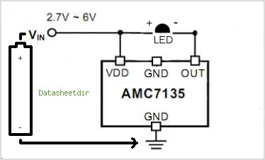
You crossed a couple wires there: the 7135 regulates the negative. so the driver output goes to LED negative, and positive battery goes directly to LED (and to the driver enable)
I got the light to work though! lol I’ll try it the other way around. I just tried measuring amps with my DMM and it wouldn’t read anything. Not even .01. But in direct drive it’s pulling 1.61A and is VERY bright!
Thanks for the information, knew I had to be doing something wrong!
Same thing happens. So it appears that I can’t use the 7135 chip freestanding to limit amperage into the LED. Is this the truth of it? I need a board with an MCU to do this?
This makes it appear that the Red positive wire goes from the battery to the Voltage in on the chip AND the LED positive. While the Out (black) on the chip goes to LED negative AND ground AND negative to the battery.
I just tried this and got full power to the emitter, 1.61A and I’m blind. This is I supposed something like 500 lumens in my face.
So, the chip just rides the line? Meaning for me, the positive leg of the chip attaches to the lead going to the positive of the led, and the out attaches to the neg lead going to the emitter, like a monitor sitting on the lines to the emitter? But wouldn’t the full power just bypass the chip?
If I do this, with new chips, it’ll get me the 760mA and some 260-280 lumens , right?
Connecting the Positive to the Vdd to the + on the star, and then on to the + on the led, then connecting the ground of the chip to a copper bar and the - of the led to the same bar, then attaching the neg of the battery to the bar and the positive to the Vdd. This right?
In your original diagram, in post #5, there was a path from the - of the diode (and also from the OUT of the 7135) to ground, BUT that path to ground was through a capacitor.
With DC (not changing), that capacitor is basically an open, i.e., there’s no DC path from OUT and from - of the diode to ground.
It’s been awhile, but I think that they have a cap in that path is for noise or something like that.
what lowlumen wrote - 7135 chips need 3V+ on their Vdd pins (right one, when the 3 legs are pointing towards you) to work, so without that it won’t work at all.
Big wire from B+ to LED+
Small wire from B+ to right pin
Big wire from LED- to left pin
Big wire from centre pin to B-
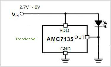
The chips can be wired in parallel so stack them on top of each other and solder the pins together, then run single wires to and from the whole caboose.
Thanks guys, it works beautimously now that I’ve been given the know how! LowLumen gave me the path, I followed it to Nirvana! With 2 chips stacked on a SinkPAD and the backside ground soldered to one of the incoming pads just for a solid ground and to hold them, I saw .72A on my DMM. Now I know these are binned at 380, but Hank gave a report a day or two ago that the Qlite 105C driver isn’t putting out the 3.04A claimed because his factory found that the chips are actually running 360 instead of 380. If this is true then the 2 chips would yield 720mA and that’s exactly what I got.
I have this SinkPAD with Nichia 219 in 5000K on a copper bar, set a MiniMag reflector on it for simulation, and the beam is quite nice. Lot of output there at this power level so I think I’m gonna be happy with this. All this is because the original driver planned for my Titanium custom light failed to come through so the mini FLuPIC is being utilized instead. I wanted to see what kind of output that would give before it got done so I could still make a choice on drivers if need be.
This shows me that the mini 3” light will have some 200+ lumens and that should serve me well!
Thanks everybody for the help, really pleasing when it comes together and I couldn’t have done it without ya!
I’ve read through this thread, but not really closely, but are you doing this with just powering the emitter from ONLY the 7135s, and with no MCU/driver other than that?
Similar to my idea here with the stars that have mounts for 7135's. (I know the star in the O.P. of the link doesn't support an XM-L or any other Cree emitter, but read down where I propose using it as a sort of "driver board" behind an XM-L on it's own star.)
I saw those awhile ago, but I was wondering, with that, would you need an additional board to provide the positive contact?
Edit: Also, why not go, literally, direct from the battery to the emitter +/-? I thought I saw a thread discussing differences of driving via 7135 vs. direct from battery, and seemed like conclusion was that going via 7135 there was a voltage drop.
My reasoning (mentioned in my linked thread) was because I'm not pursuing max output, but rather max runtime with reasonable output with the ability to also use alkalines too. It's not always about max output, right? (Please don't call me a heretic!)