Yup. Just tossed it in the freezer and I couldn't tell a difference between mode changes. Right now I'm too lazy to get it hooked up to my oscilloscope.
Let me see if I understand this correctly…the standard 105c requires “ON-time” mode memorization because it can do nothing while power is interrupted.
With the added component(s), “OFF-time” memorization is possible because the chip is “kept alive” long enough to register a long or short OFF time.
With the standard 105c - once it has been ON long enough to memorize the current mode, it takes TWO momentary switch taps to change modes again:
—–1st off/on transition restarts timer, but stays in current mode.
—–2nd off/on transition (if short) changes to next mode.
With the modified 105c - it only takes ONE momentary switch tap (short) to change modes:
—-From current mode, off/on transition (if short) changes to next mode.
Is that about right?
Thanks,
-JW
Yup, that is right. However, the chip isn't "kept alive". When the light is turned on, the MCU charges a capacitor attached to the pin. When power is cut, the cap will bleed off voltage through the pin of the MCU. When the light gets switched back on, the MCU will check the voltage on the pin to see if it hasn't completely bled off to determine if it was a short press.
It can be done utilizing the "keep alive" option using brown-out detection (the details I don't know), but doing it this way I believe requires a much larger capacitor to keep the MCU running.
I see-Thanks. A subtle, but distinct difference towards acheiving the goal.
From a functional standpoint - it’s still about the difference between TWO taps versus ONE tap to change modes, though. Correct?
On an entirely different subject - I was thinking about a single-mode application with “hidden” turbo step-down. The problem with this might be the low battery step-down:
“// Lower the mode by half, but don’t go below lowest level”
If lowest level were 255, what then?
I was contemplating what changes would be necessary to lower the mode by half, but not go below a fixed PWM level (like maybe 15 or 13).
I’m sure it’s probably a simple change, but it’ll take me at least a couple of attempts to find something that will work.
-JW
JW, I'll try to whip up the code changes tomorrow for that (or at least point you in the right direction). How do you access turbo, or does it always turn on to turbo and step down until the next time you turn it on?
Awesome work Jonny!
I had an interesting request last night and thanks to my son's sleeplessness I was able to stay awake and figure it out.
The request was this: have a single mode light capable of signaling but that will step down to a lower mode after a certain amount of time has passed.
Using the STAR 1.1 driver I made a few changes that (to my surprise) worked!
Here's what I did, working from top to bottom in the code:
1. Set MODE_MOON to 14 (this is my "step down" level)
2. Commented out (//) MODE_LOW, MODE_MED, MODE_HIGH_W_TURBO, MODE_HIGH.
3. Left MODE_TURBO at 255.
4. Defined my TURBO_TIMEOUT.
5. Commented out (//) the whole #ifdef MODE_TURBO #undef MODE_HIGH section.
6. Changed the #ifdef MODE_TURBO section to the following:
#ifdef MODE_TURBO
} if (ticks == TURBO_TIMEOUT ) {
PWM_LVL = MODE_MOON;
#endif
There are different ways to do this, I could have also just used PWM_LVL = (level) but the variable was already there.
Similarly, some of you were talking about what happens with the low voltage ramp down when there is only one mode. You can easily set it to just ramp down to a singular lower mode. Remove pretty much everything after #ifdef VOLTAGE_MON if (low_voltage(ADC_LOW)) then have it go straight to whatever PWM level you'd like with PWM_LVL = x (x = level between 0-255, 0 being off).
Nice work Richard! Seems like that could work for JW980 too.
Thanks a lot to all of you, who provided code and let us, who can’t code from scratch, participate in this.
JonnyC, especially your commenting is truly helpful. Last time I coded on my own was back in the 80’s and I never have fiddled with C before. But I now I can just try to understand what is there and then adapt it.
I’m very happy with the shutdown-option (when using unprotected cells) but what truly got me hooked was when you came up with off-time memory.
I used a 100nF capacitor - which was the closest I could find in my boxes - between Star 4 and ground.
That worked surprisingly well (cap_threshold still 100) and even gave a reasonable switch-time. Memory kicked in at about what feels less than a second or so. I ordered some 1uF capacitors, so I can follow your path and settings.
Thx
HQ
Being completely new to programming ATtiny, coding C and using Atmel studio, I ran into several situations which I like to share for others, to whom all this is unknown territory as well.
- The programmer from Fasttech (SKU 1002900) works.
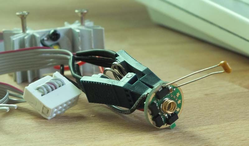
- I took a SOIC clamp from ebay, see pic above, and changed the connector. The single lines of the cable had to be adapted, the link to flashlight-wiki in the OP helps a lot, as do TomE and Sirius9 in this thread.
- I needed to install the USBasp driver that is mentioned on flashlight-wiki. Just copying the missing libusb.dll to the avrdude directory or a windows directory was not enough. With this driver avrdude can now reach the MCU.
- The clamp sometimes does not make contact to the ATtiny13A for several tries, but it always does in the end.
I position the clamp not too tight to the board but slightly higher. Then I gently rotate the clamp back and forth and test with avrdude again and again until it has contact.
- I googled for Atmel Studio 5.1 and found an installation file (“as5installer-stable-5.1.208-full.exe”) that is 631.208.120 bytes in size. It installed and works fine to load, change and compile the code. Comfy’s brilliant howto must have saved me an hour at least.
- I first changed the code using windows-editor. Line-break gave very interesting results when compiling and I had to start over again. I now change the code in Atmel studio, but turning off line-break might help as well…
- Don’t fiddle with fuses unless you know what you are doing. I did (fuse 78), it cost me a driver. I then found a ‘fuse calculator’ on this website which explaines a lot.
This is what I believe to have understood: Fuses are 2 bytes of basic settings which will not be changed by the code itself. Important for us is the MCU frequency, which should correspond to #define F_CPU. So low fuse is 75 for 4800000 and 7A for 9600000. No other low fuse should be necessary.
Low fuse 79 is like 75 but only with one setting changed: the start up time (SUT) from +4ms to +64ms. I believe this is not relevant for our use, so fuse 79 simply works as well.
greetings
HQ
Excellent work HQ, and thanks for sharing your experience!
“How do you access turbo, or does it always turn on to turbo and step down until the next time you turn it on?”
Turbo is accessed just as with the original code, so yes - always turns on in turbo and steps down until the next time I turn it on.
Here’s what I did with the code:
Set the modes as follows:
#define MODE_LOW 25
//#define MODE_MED
#define MODE_HIGH_W_TURBO 135
//#define MODE_HIGH
#define MODE_TURBO 255
Under “#ifdef MODE_TURBO”, changed the line “PWM_LVL = modes[—mode_idx];” to “PWM_LVL = 175;”
So, in effect - it cycles through 25-135-255-25-135-etc. normally, just like a normal 3-mode driver.
BUT - if left to time-out at 255 (turbo), it drops to 175. Following an off/on cycle it returns to 255 and starts the timer again. Otherwise the 175 level is skipped when cycling through modes. This is with memory enabled, of course.
I suppose that with no memory and L-H mode order, an off/on cycle following turbo time-out would cause it to go to low mode, and cycling through modes would be the same as with memory.
I’ve been using my EDC set up this way for about a week now, and I think I like it (so far).
Thanks,
-JW
Looks like you got it!
Yup, correct.
So it’s a low, med, turbo w/timeout fallback to high…low, med, turbo w/timeout fallback to high
9.8, 52.9, 100% w/ fallback to 68.6%, that is of course having star 4 soldered down, I kinda like the Hi -> Lo function myself (of soldering down star 3), but yours is quite nice too!
fyi, I'm using Atmel Studio 6.2 BETA now, no probs, here: http://www.atmel.com/tools/atmelstudio.aspx
Well, I’ve managed to get single-mode operation (capable of signaling) with 1-minute turbo step-down and ADC_CRIT warning/cutoff, but can’t seem to get ramping-down on ADC_LOW.
Still trying, though.
I just thought a configuration like this would be good for a hard-driven C8 that doesn’t normally need to be multipurpose like an EDC.
-JW
Whoops, major bug in the off-time firmware that disabled low battery detection when compiled without a turbo mode (disabled WDT which caused it to never wake up from its sleep state). Will have the fixed code up on my site soon in case anyone downloaded it yet.
Cool. STILL haven't gotten around to trying it! Been trying to catch up on everyone's orders...those take priority over tinkering time these days. I will also share my multi-group code, different turbo stepdown code, etc. once I get it cleaned up so that it doesn't look so...um...crazy. I don't really know what I'm doing but sometimes I get lucky and make something new work! 
How do I post code?
When I try copy/paste, several parts will disappear with save/preview:
- some brackets and what’s inside,
- double ‘=’
- line breaks missing
Can someone give me a hint please?
Thx
HQ
Probably best to upload the file to google docs or something similar then share it, that way we can all see the exact same thing you see. I also think that pastebucket is a good solution.