In case it got lost last time I mentioned it - Coilcraft do free samples. I got 10 of the exact inductors required for zero dollars. I didn't even pay for postage. And this is in Australia. If I can get free sh*t in Australia, there is no doubt you can do it in the US/Europe as well.
EDIT: In case you want to buy some (because we know they work so we may as well reward the company for making them) you can get them here:
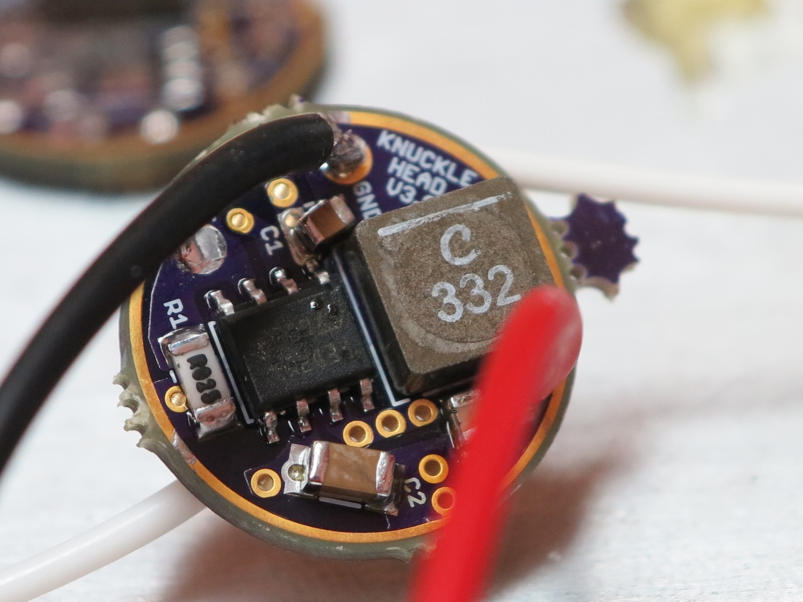
I've also added a picture of Dale's handiwork to the first post. I finally got my voltage regulator ICs today so I can finalize my own build too.
Question for any of the coding gurus out there. Is there anyone willing to create a basic firmware specifically for this driver, that is well commented and easy to edit (eg. add/remove modes etc) but that has a section for low voltage detection built in that can automatically account for 1/2/3/4S battery packs? Just a firmware that any DIYer can take and edit to function how they want. I really don't know how it would/could work. The idea is that we can nail down what the voltage divider resistors should be to allow for all four possible battery pack voltages. Probably need some input from an experienced coder for this. I was thinking a basic voltage detection function could be written that makes it easy for someone to use the results in the rest of the code. Really I have no idea.
Details, one more little one. The low is now set to a number 6, should probably go to 7 as it seems to flicker ever so slightly. This is with 2 or 3 cells. With one cell it doesn’t want to work at all with the setting on 6. This is, of course, in JonnyC’s STAR firmware.
This firmware makes us of Star activated moon mode. How would I activate that on this driver or is that possible? Might have to work that in with the firmware, and then spread out the modes a bit. I want to put it in a light and play with it, but not one of the difficult lights as I’d like to be able to remove it easily. But flashing it should be pretty easy as the MCU is on the spring side. I’ve got a Ryan copper pill for the Convoy C8, might need to get another one and have someone make me a battery tube extension for it. Hmmm….
Also note that the voltage divider resistors used for cell voltage detection (R2 and R3) are 10k and 3k and will not function properly with standard NANJG or similar firmwares. These values are only really suitable for 1S battery packs. The ideal resistor ratio is 100:7. With this ratio at 16.8V (4 fresh 4.2V batteries) this gives you 1.1V to the MCU, down to 0.2V at the MCU for a depleted 1S pack (3V - this driver will not function below 3V). Possible resistor values are for example (R1/R2) 10K/0.7K, 100K/7K etc.
Would one of Dr Jones firmwares be easier to modify? (minidrv )
there are no stars on this board, and seeing as to how you have to program the mcu yourself, there is no need for all those extra fancy features?
nvm. Just realized it doesn’t have low battery warnings.
Low battry warning will be different for each cell setup
2S, will be different from 3S because of higher voltages (not to mention you MUST run the MCU thru a zener or the higher than 5vdc will more or less smoke it
We’re talking about R-2 and R-3 right? I’m thinking about putting this in an M3 head with an MT-G2, using 2 extension tubes on the L2P host for 3 cells total to supply the 6V emitter. How does that affect this buck driver? Where do I look to figure out the proper resistors to use for that instance?
Wight taked about it a few posts back, but as far as I am aware you want the output of your voltage divider to be no more than 1.1V on full cells. Use a voltage divider calculator to determine the ratio. Like this one. Start simple. Make Vin 12.6V (3x4.2) and R1 10000. Then enter random R2 numbers until the Vout gives you 1.1V or less. For your example, 10k and 0.95k works. It's then a matter of finding the resistors (or as close to those values) in the size you want (0603). You can adjust the values provided the ratio remains the same. In this case its 100:9.5.
If you can't find a 0.95K resistor, you can change the value of it, to say 1k. But you need to increase the value of R1 to account for the increase. Just keep the ratio the same. You don't need to be bang on either, you can have a max Vout less than 1.1. Having it at 1.1 just increases the accuracy.
Yes, so you cannot use an internal Vref for battery cell voltage detection. The voltage divider that feeds pin 7 of the MCU is fed directly from the battery.