Recently bought a SupFire L5 from Richard (RMM) at MtnE (mtnelectronics.com SupFire L5) and nicely impressed with the quality/value. The finish is a flat gray and feels a lot richer than the price range of this light. For me, it's almost perfect for this form factor, just really wish it was a true SS bezel, and there was more beef to the heat sinking internals. After a few days, noticed the button (e-switch) was acting up, not working consistently, and mentioned it to Richard but wanted to find the cause first before doing anything bout it - was it the switch itself or maybe the driver getting flaky. So did some poking around on the driver, and it did seem to be the switch itself - that's sort of bad news, not knowing where I could get a replacement PCB mounted switch to fit, and if I did find one, how much, and really didn't want to bother Richard with it.
So, I only had one type of spare e-switch:
100PCS Tactile Push Button Tact Switch 4mm x 4mm x H1.5mm 4-pin DIP #1292
bought for $3.75 w/free shipping off of eBay, seller: electronic_diy_honest, this is what it looks like:

It's tiny, but works pretty well and I got 100 of them...
So, it looked like if I sand down the mounted switch, I could possibly mount this thing vertically on the switch, still have it positioned properly for the rubber switch boot, and can wire it up to the driver - that's what I did. Here's the button and plastic mounts sanded down:

Perfectly flush:


Here it is mounted and wired up. It's bit blurry, but the 2 tabs on the bottom are soldered to ground, I attempted to solder tabs on the back but don't think those held, so I added some super glue from the top to get between the old switch and new one - seems to hold pretty good. I wired a top tab to the point of contact on the old switch that goes to MCU pin #2 (that's the e-switch input). Funny because we use pin #2 for the ATTiny13A's... Maybe that unmarked MCU is the same?

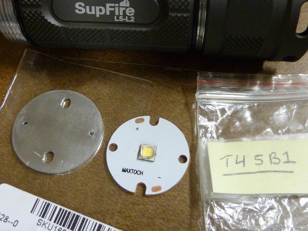
While I was at it, though I'd do a pseudo "Mod Option #1" (i.e. Stage 1) mod, using a warm XM-L2 (T4 5B1) mounted on a MaxToch 26mm, and tweak up the amps a little. Well, actually I was forced into upgrading the LED because I attempted to route around the resistors, like we do on the F13 clones, but with the LED +, not LED -, and it went really bright for a second or so, then poof - popped a LED fine wire, just one of two. I know that because the LED would still light up but very dimly, and I could see in the silicone a bubble of sorts that appeared around one of the gold wires.
Notice below I removed the pill shelf from the L5. It easily pushed out from the driver cavity. Again, unintentional because I was trying to push off the MCPCB that was epoxied down through a wire hole, and instead of pushing up the MCPCB, the entire pill shelf pushed up  . Well planned mod for sure...
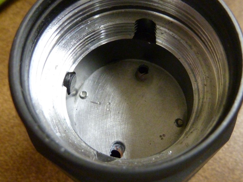
The shelf is only about 1.25 mm thick, so the MCPCB's are thicker  . So with the shelf out, it's a lot easier to work on the LED MCPCB mount. So, sanded it down smooth, drilled and tapped holes for screws, etc...
Added a single R500 resistor. The resistor math said it should do about 3.25A. I wanted to keep the mod relatively mild, and not planning on adding any heat sinking at this time.

here it is re-assembled - pushed it down tight, added some AS5 (a little) at the small ledge the shelf sits on - maybe that helps. I used GC Extreme between the polished MCPCB and pill top shelf:
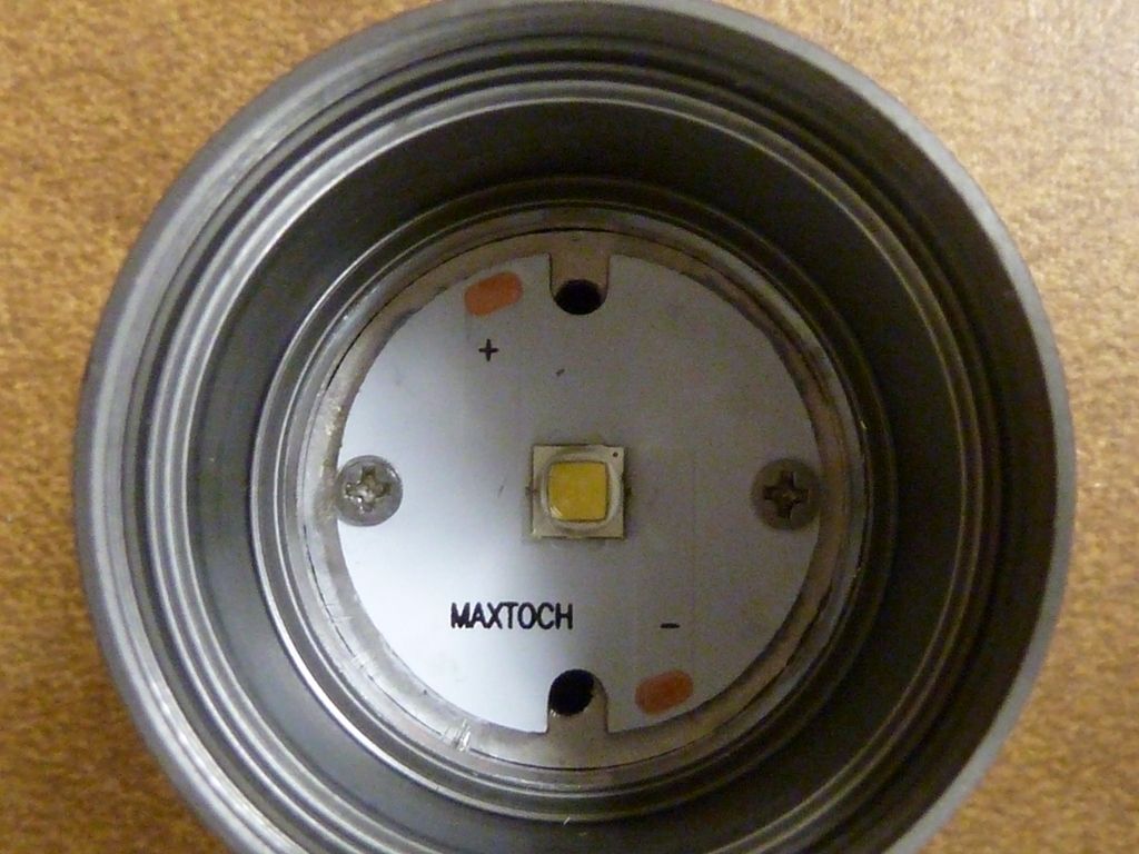
here's the top view. Nice and neat - I used the round LED alignment piece, but not the big plastic shield (these parts not shown) that was on there originally, that covered the entire MCPCB:
After assembly, the initial tests were disappointing, getting only 2.57A at the tail. However, I failed to realize the KK 26700 cell I was using was somewhat down at maybe 4.0v and I didn't have the spring wired yet. So, a quick test in the lightbox revealed a big benefit to copper wire the spring. I can easily determine that by testing it assembled, than test it with the tailcap off and using a heavy wired to jumper the battery - end to the body.
Before the tail spring wire: 660 lumens OTF (30 secs)
After wiring the tail with 22 AWG: 796 OTF -- Wow! A 21% gain!!
I don't have pics, but the tail spring sits in the tail unattached/loose, under a brass cap. So, I simply added the 22 AWG copper wire down the middle of the spring, that sat it back in the assembly the way it was. Only other thing I did was treat the top and bottom of the spring with NO-OX-ID. The 21% boost was even slightly higher than what I recorded with the heavy jumper wire - this I've seen before, and I sort of explain it by the relatively poor connection the jumper wire has to the body from simply holding it against the threads.
So I then went ahead and wired the driver spring to see if I can record a higher tailcap amps reading. I did get 2.72A now, a small bump from 2.57A - interesting...
Then finally got a fresh KK 26700 off the charger, and re-tested:
- KK 26700 at 4.22v, 3.11A at the tail, lumens: 928 @start, 904 @30 secs, throw: 23.5 kcd (measured at 5 m)
Should be noted I had this L5 already configured with a 37 mm UCLp lens.
As a reference, pure stock #'s I measured, probably a XM-L2 T6 1A (I think with a fullly charged KK 26700):
- 2.20A at the tail, lumens: 748 @start, 687 @30 secs, throw: 18 kcd (measured at 5 m)
I really like the way this limited mod came out. Great tint and pretty good output and throw, plus a respectable runtime from a cell that has 5400 Mah capacity (rated at 5000, but the Opus charger says between 5300 and 5450 or so). Not too crazy about the stock UI of course - 5 classic modes, always starts at hi (hi-med-lo-strobe-SOS), and you can turn the light off from any mode by holding the switch down for 2 to 2.5 seconds -- way too long... It could be a worse UI, the hi-med-lo modes are actually nicely spaced, and nice to have the hold long OFF feature.
The ultimate mod though would be to add heat sinking, run it at a bit higher amps, with around 4A or DD using a BLF17DD piggybacked, and my e-switch driver. I really like side switch lights though - much better UI's are possibly and for high amps, the switch is not taken a beating of the power cycles and is not in the circuit adding resistance.
For the replacement switch, I'm really liking it so far - it is working very reliably, but doesn't have the click feel the original switch had. Unfortunately, many of those PCB mounted switch have a button that is rectangular, and seem to be less reliable if they are pushed in slightly to either side, and with the typical slop the driver mount has in these hosts, they are susceptible to problems. This replacement switch, mechanically, seems like it will be better because the button is round and all metal, unlike the plastic stock rectangular button. Time will tell if it holds up.
For $3.75 for 100 of these things, I'm hoping to find more uses because I got 99 left .
Update Oct. 8, 2014:
Wanted to boost the power a bit more, so went ahead and added another resistor. While I had it apart, though I'd add some missing pictures from above.
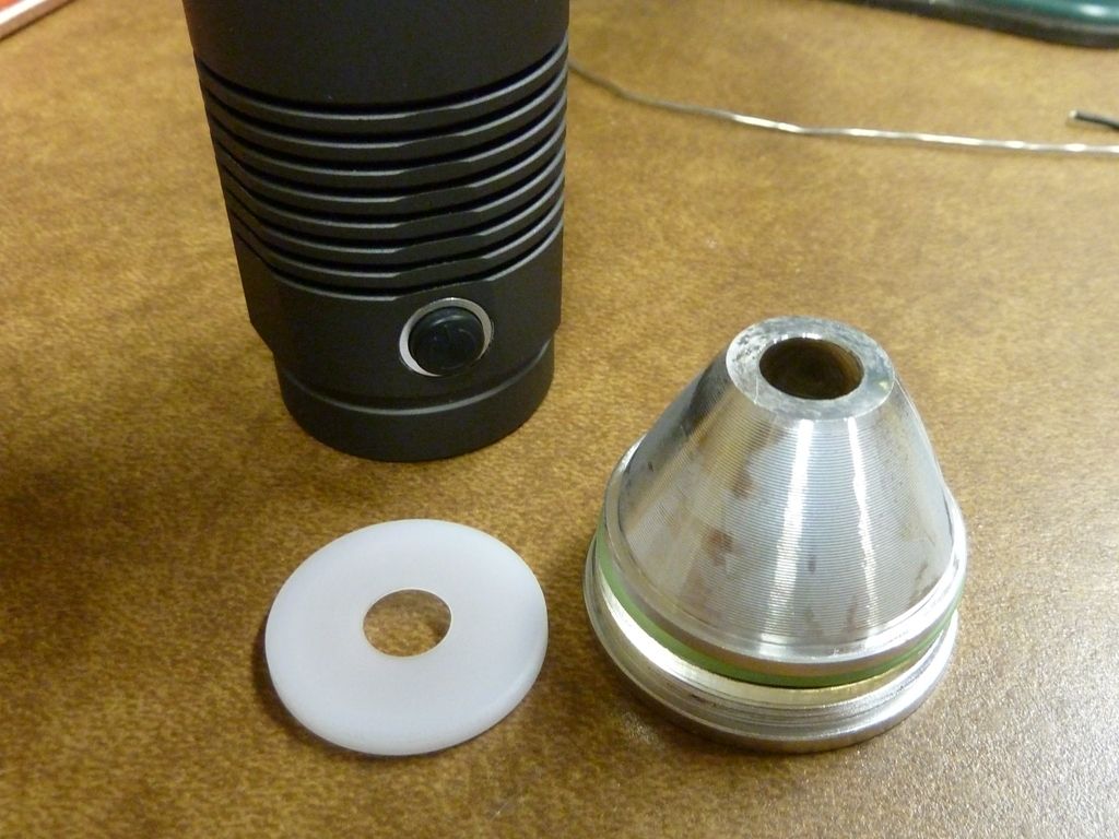
Here's details views on the tailcap assembly. The housing is quite chunky:

All the parts with my 22 AWG wire added to the spring:

Close-up. I left the spring just sitting in there, and seems to really work well based on the 21% bump in output:

Although the retaining ring is plastic, it's pretty hefty and should hold up well:

Driver side, wired up with 22 AWG:

The "front stack". I replaced the stock o-ring with a thinner one to make up for the extras thickness of the UCLp lens (shown):

This is the plastic MCPCB cover, which I no longer use:
Fully mounted/wired, really like'n these MaxToch MCPCB's. I still use the stock LED alignment piece:

View with the extra resistor (R620), and another view of the mounted switch. Not much of a bump - results below:

After adding the R620, again, I expected a more significant bump, but with the same make cell, KK 26700, and at the same level of 4.22v:
- KK 26700 at 4.22v, 3.37A at the tail, lumens: 972 @start, 945 @30 secs (no throw measurement)
8.7% bump in amps resulted in a 4.5% bump in OTF lumens. Probably about right...
Some Measurements:
- Lens: 36.8 mm x 1.42 mm
- Reflector: 36.8 mm O.D. x 33.3 I.D. x 22.65 mm depth, 9.0 mm hole
For Reference of reflectors in roughly the same size head:
- F13 clone Reflector: 36.8 mm O.D. x 34.5 I.D. x 26.15 mm depth, 6.9 mm hole
- Eagle Eye X6 (BLF Edition) from J.M. review, Reflector: 29 mm I.D. x 24.57 mm depth
- UniqueFire M6 Reflector: 35 mm O.D. x 32 I.D. x 25.3 mm depth
Note: all my lumens and kcd measurements are "my own" taken on an older LX1330B meter - kcd taken indoors and lumens in a PVC constructed lightbox, accuracy can be freely debated (CYA all the way...)


 .
.