Again, I haven’t looked at the circuit at all, but this board looks pretty good. You could always add labels and make the traces wider, but neither of those is really necessary
I’m not overly worried about the trace sizes it’ll be such little current but I will do so and add labels when people think it’s ready to try.
I like the idea and would love to try a set.
I want to use these in a few Solarforce lights. They take a 19mm board with a tall hollow cup washer to space them out. I will likely start with 20mm boards and sand them down, but it would be great is someone could grow the 17mm or shrink the 20mm to 19mm's. I am afraid that if I sand down the 20mm board the components will be to close to the edge and hit the cup washer.
Does anyone know where to get these cups??? They are 19mm in diameter and 6.88mm tall. I also need some of the taller springs that Solarforce uses, they are about 14mm tall!

Matt
You should be able to bin the plastic adaptor if you have some basic tools like a drill and use a flat washer with the correct inside and outside diameter that fits over the boss on the switch. I usually find a washer around the right outside diameter and drill the inside diameter out to suit.
I am going to get a 3/4” nylon hollow spacer to build them from. Spacer stock
Was kinda hoping someone knew of a source for them, you save time.
I think it’s less about capacity than trace integrity. Too small and you might lose continuity or an entire traced during fab. If you label them we can tell if they’re in the right place. Then we can try it out. I can read a schematic ok but not well enough to guess. Thanks for running this up.
v005
I’ve increase the path size as much as I can.

Update. I got it working. I skipped repairing the busted BLF-A6 driver for now and went to the other BLF-A6 light that still has its working driver. Installed the 680 Ohm bleeder (now without drilling holes, please admire my stunning solder job ) and used the lighted tailcap that was already finished. Also I made a clear plastic 'tail cap clamping ring' (is there a name for that?) from a piece of 2mm thick perspex. Lighted tailcap and user interface both work fine now! :-)


Hmmm, I just ran the BLF-A6 on high for a few hours to drain the battery, and even at 2.9V the blue led stays lit. I had adjusted the resistors so that it would go off somewhere in the middle beteeen 3.4V and 3.8V, but it clearly does not do that. The resistor values were determined in a 16340 light, so perhaps the blue-light-off-voltage is dependent on battery type (which makes no real sense to me). Going to check that by swapping the lighted tailboards from the 16340 light and the BLF-A6.
TBC
I'm not sure if you are pulling the battery to measure voltage but if you are it could well be the 16340 's voltage has sagged a lot more in use and bounces back to a higher voltage when measured whereas the larger battery is more constant.
I just thought about what I wrote and its nonsense in this case. Sorry.
Actually that was my first thought too, with these leds going on when the flashlight is off it is confusing. But indeed, the tail leds work at such low current that the voltage of the battery under their loads must be virtially equal to the resting voltage. That makes it strange that the type of battery matters, voltage=voltage you'd say.
Just swapped the lighted tailboards of the 16340 light and the 18650 light. They have different resistor values so if swapping does not change their behaviour, the behaviour is not battery-dependent.
Unfortunately that is not the case, the behaviour (at which voltage the blue led starts dimming and eventually fades away) is hugely battery dependent. So for every battery type the resistor set-up must be seperately determined. On top of that I found today that for a 18650 battery the blue led stays lit at any voltage down to 2.9V, probably with any set of resistor values, so this low voltage indication only works for small batteries. Well, at least the colour leds look cool 
Let's hope that the low voltage indication circuitry with the transistor will give better results :-)
Could it be that the internal resistance of the 16340 battery is higher than that of your 18650 30Q? Don’t know how I can explain it, but it the only battery related parameter that has not been discussed up till now.
Internal Resistance is my bet
Okay, so I figured out the issue. This is a good thing, because I was getting tired of messing with it. It ended up being nice and bright, helped by a clear switch boot that I found. And by found I mean I purchased a $24 Olight on panjo just because it had a spare clear boot, and I thought it would fit. That either speaks to my desire to finish the project as imagined, or of my level of obsession.

I gotta say, these Solarforce tailcaps are a pain to work with. I’ve got the BLF manker A6, it looks like the 17mm will fit right in without modification. I will probably try that next. I do have a 6P that I’d like to try as well, to see how that goes.
~D
I'm glad you got it working DrafterDan :-)
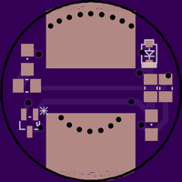
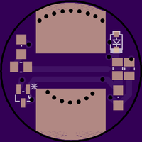
Tonight I made a new version for my EDC light. Instead of aiming for a low voltage indication, I tried to make a permanent moonlight mode. In my spare parts box was a loose XM-L2 I did not know the tint/bin anymore, somewhere 5-ish80CRI I'd say. Used that for the tailboard, and managed to accidently dedome it in the process, which was good for the moonlight tint. I needed the disc-sander to adjust the shape of the led, that led-base material is really hard stuff! The XM-L2 was mounted across the led+resistor pads because it needed no resistor for best output. The red led on the other side of the switch, with 12kOhm resisitor, is just for aestetics :-) (I messed up a trace, hence the extra piece of wire). The bleeder resistor in my EDClight is still 680Ohm.


The current through the two leds is 185micro-amps, so on a 550mAh 16340 battery it should drain the battery in four months. I measured the light output at 0.004 lumen, which is plenty light to find my way in a pitch dark bedroom (one of my uses for moonlight).
I just realised that this light now has a range from 0.004 lumen to 800 lumen, a factor 200,000, who beats that 
I like it!
I think it’s ready. I’ve looked over the circuit and it matches the diagram.
Now has 0805 pads, and the largest traces that were reasonable.

![]()