Yeh that should work!
I have done it once. Now I am building PilotDogs driver that has a bleeder pad set. Search for “PD68 double down”. Good driver!
Matt
That’s exactly where I solder mine usually, TK. 470ohm should be fine. I use 560, and I think djozz uses 680. Technically the highest number that retains functionality is best.
Highest which retains functionality? What would it do if the value was too high?
I had to adjust the values quite a bit in the BLF-A6 firmware to get the medium and long presses to time correctly. I may try a small reduction of the bleeder to see if they will come more into line. I am thinking something in the mid 400’s.
As far as i have figured out, without the bleeder resistor in place, power is being pulled through the voltage divider and through the MCU itself. The current through the led circuit in the tail is enough to either keep the MCU powered up or at least keep the OTC from draining at all. So without a bleeder resistor or with too high of a value, mode switching completely breaks down. It essentially turns the light into next-mode memory. Maybe since you’re using the 25 not the 25v, you might be able to get away with a slightly higher resistor value. I remember when I was first working on this that 1kohm was too high of a value for memory to work correctly. The next value that I tried was 560ohm and that worked, so I’ve stuck with it ever since.
Some drivers (that don’t use the OTC), don’t actually need the bleeder at all.
Now, I don’t have a sphere to measure lumens/efficiency of before and after the tailcap mod. But technically the bleeder resistor is always there, leaking a bit of current past the driver and led. That small leakage current shows up in tailcap readings, but not to the LED. Based on my eyes I don’t think it’s much, but I can only speculate. Maybe Djozz would be willing to do that test.
Are people still able to reflash installed MCUs with that bleeder in place?
I’ve been able to write data but when I read it back I get errors. I’m not sure if it’s a physical connection issue like usual, or if the bleeder might be interfering.
I can’t think of a reason why the bleeder would cause that. I’ve never had any problems reflashing with it installed, but I’ve never tried to read back once I’ve flashed either.
I spent quite a bit of time flashing different code on the last one with the bleeder in place and never got a failure.
I have put a few together with 105c drivers with various numbers of 7135’s and have not yet needed a bleeder on the 105c.
This is the ultimate dresser for a light, I get more comments at work. I do not own any lights with trits, and now likely never will!
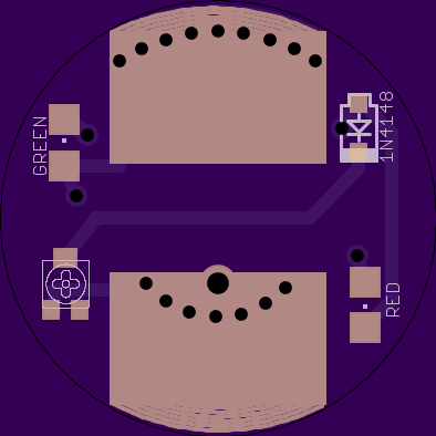
I am not sure what is wrong with my build. The board looks good, the LED’s both light but the main light does not work correctly. I used red LED’s, really wanted a red one, have only built blues so far. I used 1 4.7k resistor with 2 LED’s and it was very dim, so I cut the resistance in half with a second 4.7k resistor and the light output got better. But, with 1 or 2 resistors and a 105c driver I could not change modes and with a FET+1 driver and a 560 bleeder I had no mode memory and very erratic behavior.
I am sure that it is an OTC problem with the FET+1, but did not expect to have any issues with the 105c.
Any ideas?
Thanks Matt
Anyone had a chance to test pyroson’s transistor board yet?
I think Djozz was waiting for the parts to arrive
I never got the transistors, lost in the mail or something. Wrote the ebay-seller and he re-sent them, just got them yesterday. I will lego-solder (do not have the pyroson board yet) the circuitry up one of these days and see what works.
I’ve ordered some boards and will get the parts soon and give it a go
After finally trying a lighted tailcap, I’m a fan. ![]()
… but I was too lazy to order the parts and actually build it.
It seems to last about as long as Zebralight’s lowest firefly modes, with roughly comparable output, but works in a way which looks better and seems more useful. Would be nice to be able to turn it off during the day though.
We had discussed implementing a light sensor, but decided it wasn’t feasible because it wouldn’t respond to artificial light.
I’m still hoping to find a tiny slide switch to fit under the spring
Any light with tail cap lock out can turn it off.
Why the diode?
So would then these fit? http://www.ebay.com/itm/20x-3305SMD-50K-Potentiometer-mounting-single-turn-50k-100mW-SMD-25-/201437549289?hash=item2ee69d12e9:g:7p0AAOSwFnFWBrA4

(this one is 0-50kOhm)
Drops the voltage by 0.6v protecting the LED and reducing excessive drain. They should fit but cant say for sure about size this is just a quick look but will try and find a reliable source that I can get the correct size then will create and test.