so the ntc is connected to the driver with a wire, and the ntc is glued somewhere away from the driver ?
and the driver has a temp protection already, without the ntc ?
is that right ?
, so using the ntc may not be helpful, or worth the trouble ?
NTC is used for temperature regulation so the flashlight doesn't burn your hand, while the driver has temperature protection to keep the components from overheating.
The very small NTC is necessary for the driver to have thermal protection. Without it, the driver doesn’t know to step down due to heat and could be damaged if a light is run too long on the highest setting with a high discharge cell… especially if the 9A or 12A option is chosen with a triple or quad set-up.
Yes, two small wires are soldered onto the NTC… one on each side, and these wires are then soldered into via’s on the driver as indicated in the OP.
In my case, I used one wire for the switch… I figured the ground was common and not needed but I did solder a wire from the other side of the switch to ground to be sure it was in the loop.
So, in theory, if you wanted to run a 9A 2 cell variant with moon in a light with an e-switch you would have a lot of additions and changes to make to this driver. It’s not particularly difficult but these modifications do indeed entail soldering extremely small parts. I’m talking about 21 soldered contact points for this to happen. So yes, it’s a pretty good little challenge in and of itself. ![]()
Will, check post 39 and 40… in post 39 it was asked if the NTC could be left out. LED4POWER answered in post 40 saying that if you don’t use the NTC you have no protection to keep the driver from overheating.
Hi,
it was a bit hard to solder all parts (especially eSwitch and NTC Support), but finally i got it managed. I placed the NTC on the inside of the anodized pill and fixed it there with some Fujik.

Greetings
Kenjii
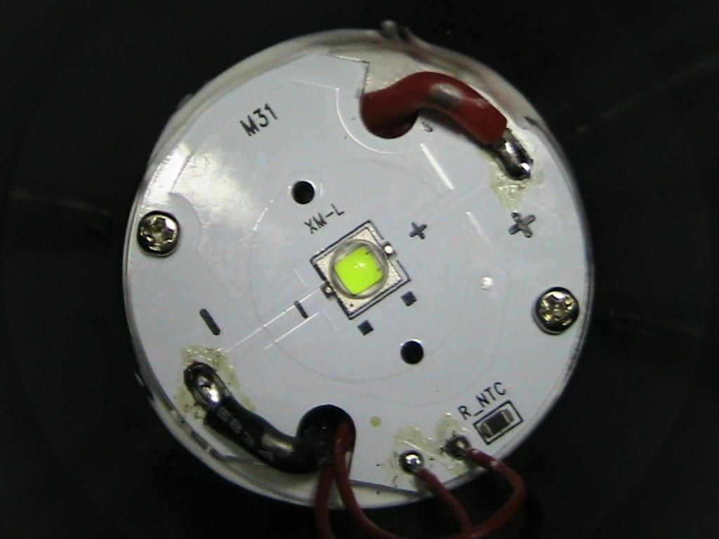
The idea is to mount NTC somewhere in flashlight "head",but the simplest way is to mount ntc is on led mcpcb,because it's flat,thermally good connected to head,and top of mcpcb is electrically insulated from body(very important).
Ideally,there would be solder pads for ntc on mcpcb.just like for LED,I've seen picture of olight (I think) mcpcb with the exact same thing,but I can't find it now.
Edit: found picture
So I asked hank could he add NTC solder pads on noctigons,and here is the answer:
"For the NTC footprint, we are glad to add the feature on our Noctigon boards,
but unfortunately, we still have large Noctigon boards in stock, so, it will
be quite some time for us to produce the new batch board with the NTC footprint."
So,for now my preferred method is to put tiny amount(small dot) of Arcitc alumina on noctigon(close to edge,so you don't have problems with reflector/optics placement),then put NTC on AA (amount of AA must be small,because you don't want AA to cover solder pads of NTC) and leave it until AA hardens.Then solder 30awg wires from driver to NTC pads.
Check pictures in this thread:
https://budgetlightforum.com/t/-/33824
LD-2 has two different thermal protections:
1.Driver overtemp. protection(internal sensor)
Always active,purpose of this protection is to protect driver itself from overheating;threshold is ~105C,and driver goes to complete shut-down.If this protection activates,it means you don't use driver the right way-thermally.Either your thermal path is not good enough and/or battery/led set isn't "optimal",more in OP.
2.Flashlight overtemp. protection(external NTC sensor)
Active if you connect NTC,purpose of this protection is to protect flashlight from overheating;threshold is ~55-65C(depends on flashlight thermal properties,ntc position,etc.).This protection replaces inaccurate time limited protections( popular "turbo timer"),and it's normal thing to happen in smaller high power flashlights. Driver steps down to medium mode and further regulate current if it's necessary.
Maybe one confusing this is why driver and flashlight temperature aren't the same?
Well,LD-2 is linear driver and burns extra voltage into heat,and because there isn't a simple way to put mosfet(heat genereator) directly to flashlight body,mosfet could run hotter than flashlight.
I hope things about thermal protections are clearer now.
Thanks for the explanation.
These are very High Quality drivers, I like them a lot! When are you going to come out with 20-22mm size driver? Money waiting to purchase!!!
Thank you for the explanations.
I used AATA to affix the NTC on the side wall of the anodized driver bay, closer to the emitter shelf than the driver. (about an 1/8” above the emitter shelf) I wanted it to be there, but not TOO sensitive, as I like to run a light on the hot side but not dangerously so. ![]()
I used thick 18ga wires to “float” the driver above the stock contact board, hoping that the oversized positive and negative connections will help to carry heat away from the driver and into the contact board. Almost potted it, almost added some copper to the top of the MOSFET to help there, but didn’t. Now that I know it functions well I may have to do that.
led4power: what is needed to run 3S? I see changing one 0402 resistor is mentioned.
sorry i did not read thw whole thread (i use my mobile…)
is it possible to use 4 cells for a 12V emitter?
Yes,just one resistor needs to be changed under "6V parts" section. Which emitter do you want to drive?
xhp35
but maybe also xhp50/70 6V also (different lights)
One of them has to be changed to 375k, but I don´t know which one. That´s interesting for me also.
Hi. Is it correct to assume that moonlight mode does not have low voltage protection?
Low voltage protection is always active, it doesn't depend on selected mode.
Cool. Thank you ![]()
Sorry,somehow I didn't see this question:

One resistor needs to be changed,and for 4s operation OPAMP chip needs to be replaced also,as in picture. Resistor should be 750kOhm for 2s operation(stock),375kOhm for 3s,and 250kOhm for 4s. OPAMP for 4s should be OPA172IDCKR(quite high quiescent current ~1.6mA,but little bit cheaper ~2.3$) or AD8641AKSZ(low quiescent current ~200uA,but even more expensive ~3.5$).
If you don't have required values,two 750kOhm resistors can be stacked for 375kOhm,or three for 250kOhm(well it requires some skills and steady hand to stack 0402 resistors).
3s and 4s configurations could generate more(too much) heat in driver,it depends on LEDs,batteries and max. current,so it's always good idea to approximately calculate max. dissipation and ensure good cooling/thermal path before using LD-2.
Ok, got it. No problem…
Thank you!