Just got my Lii-100s; cell voltage 4.25V and 4.23V when taken out after being finished for a while. I don’t like that and modded R6 with a parallel 3M, should be 4.15V then, which I like (longer battery life), testing that now.
Thanks, sixty545!
My pleasure! ![]()
I love that charger - have eight now. Made one 50/100 mA and one 200/400 mA, planning for one 3.8 V for storage level.
I no longer worry about cell life.
That’s what I said after passing 8th grade Biology… :GRADE:
My understanding from reading HJK”s reviews is that acceptable Li-ion chargers charge at 4.20v +/.05v not “to” 4.20v so acceptable charge voltages are between 4.15v 4.25v.
I now have 2 Lii 100”s & they both seem to charge at 4.22v (according to my testing) & I have never seen a cell come off them show above 4.19v.
I also have a Lii 500 that also seems to charge at 4.22v & again I have not seen a cell “hot” off the charger above 4.19v.
My Opus BT 3100 v2.2 seems to charge at 4.20 & I havent seen a cell above 4.19v.
My Nitecore D4 shows that it charges at 4.20v & I haven”t seen a cell above 4.18v off that charger.
Cell voltage drops immediately charging has stopped.
If you want to get a few more cycles then marginally lower charging voltage might get you that but personally I want my cells charged as “fully” as possible without being dangerous & if that means losing a few cycles then fair enough.
I use an Amprobe DMM with heavy duty leads & think that it is pretty accurate.
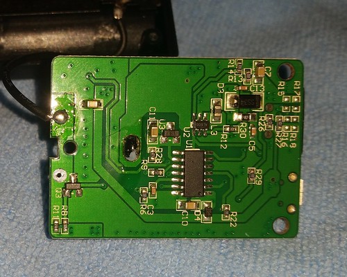
New version of the Lii100 with different cover art and a different revision board. I have not got to test one yet, starting a charge soon to check termination voltage.
Tested 2 now, the terminal voltage is 4.24 volts and the cell upon removal is at 4.22 volts!
Interesting, will wait for the results.
That new Li-100 looks to have Colaier like aesthetics: http://www.gearbest.com/colaier-_gear/
Cheers ^:)
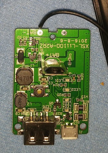
Does anyone know the value of R6? I lost mine when I desoldered it ![]() It think it said 18D could it be 150k?
It think it said 18D could it be 150k?
Yup, it was 150k ohm stock. I changed it to 152.6K ohm. It went from 4.256v to 4.222v :+1:
sixty545, we don’t have smd resistors here and ordering in some would take over a month and cost way too much. Any suggestions? Can I simply replace R5 or R6 with a specific 1/4 W resistor? (If necessary, I’ll make holes in the body and have the resistor outside…) Charge voltage of a LiIon is just over 4.23V.
Thank you! ![]()
Isn’t 4.23 still within tolerance? Protected cells don’t even trip until 4.3 volts. The cell will degrade from age before a 4.23 charge effects it
I prefer my cells at 4.20 V or just under. ![]()
The resistor kit mentioned in the OP now cost $1.19.
If that is way too much You can mount across R5 any combination of resistors that make up around 6.1 MOhm if you can find the space. Or you can use the solution in post #32.
If you replace R5 or R6 with another type of resistor make sure it is a 1% type 150kOhm.
Myself, I would wait that month to avoid the hassle.
It’s not a matter of cost of the components. Shipping to me would be $3 ish US and customs+ tax, as much as $12 US, all for $2 in parts. lol. Principle and minimal patience are the issues ![]() Thanks for the response
Thanks for the response ![]()
I have the same version as you. I just got it today from GearBest. It’s charging to 4.25V (in circuit while charging). Do the mods in the first post still work on this version. I’d like to lower it to 4.20V.
I used a pencil to ‘shade’ R5 to create a high resistance parallel resistor and it worked, sort of. The charger stopped charging a LiIon at 3.7V! Hahhahah. Maybe a little less Omph would have been more effective. ![]()
Secondly, I bought a 146.8k ohm, 1/4W resistor and replaced R5 completely. On first charge, a LiIon cell was charged to 4.174V, a 4.35V cell, to 4.293V and an AAA Eneloop to 1.44V. The 1/4W resistor has more than enough space to fit inside the charger if it is laid flat on the PCB. (Older version charger.)
@stereodude:
It should work just fine. Check that R5 and R6 are marked “18D”. It means 150 kOhm.
I recently modified another 3 pieces. They did not have the yellow/ orange markings but they had new dates on the circuit boards.
@eebowler:
Good job! :+1:
Are they 0805, 0603, something else?
Edit: They are 0603 (not metric 0603).
This is a great thread.
Thanks sixty545 for bringing this up and describing so well! And kudos to freeme and mattlward, the pictures helped a lot.
These chargers are really good even in stock form: reliable, many options, very priceworthy, screwed and not glued. I will play with both, termination voltage and charge current.
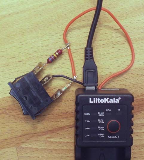
In the case of termination voltage I’m aiming to have the option to select 4.1V (for cell lifetime) and 3.8V (for storage). With termination voltage I mean the resting voltage of the cell after charging, not the max voltage spikes while charging.
After some calculation I soldered some scrap parts, which indeed did turn out as planned. ![]()
The black wire is soldered to one side of R5 and the red wire to the other side. The switch is on-off-on type and lets 2 different resistors to be added in parallel to R5. Off position means R5 stays 150k giving about 4.21V.
With 3M3 in parallel to 150k, resulting in R5 = 143k, the cells are charged to 4.11V.
With 680k in parallel to 150k, resulting in R5 = 122k, the cells are charged to 3.82V.
I tried 4 different cells, results are +/- 0.01V.
.
.
Now I need some smaller switch and resistors ![]()
After having opened a 2-bay Lii-202 it looks that these are similarly moddable, so I will continue there.