Super nice work!!!
The holes were slightly over size to start with. I think I put a slight bend in it which snapped it off. Tapping on the edge of a step probably didn’t help things either. My fault.
How do you fix that? My method involves a hammer and a high proof lubricant.
Good question. I’d hoped you would be able to tell me the answer. I will have to enact plan B to fix it. I have an idea but not measured anything up yet.
What;s next is kind of like the old joke about proper bolt torque: “Tighten it till it breaks, then next time a half turn less” :person_facepalming:
Locate, drill, tap, then mill the shelf. Also you might chuck the tap in a drill press turning the chuck by hand with the spindle feed free to follow down as the tap pulls in. Holds the tap as straight as anything can, just don’t try it under power or it will break every time. I imagine you know all this but I figured it might help someone else some day ![]() As tough as my old calloused fingers are I doubt I could feel a 2mm tap binding so I’d break plenty
As tough as my old calloused fingers are I doubt I could feel a 2mm tap binding so I’d break plenty ![]()
Phil
Update 19.2.16.
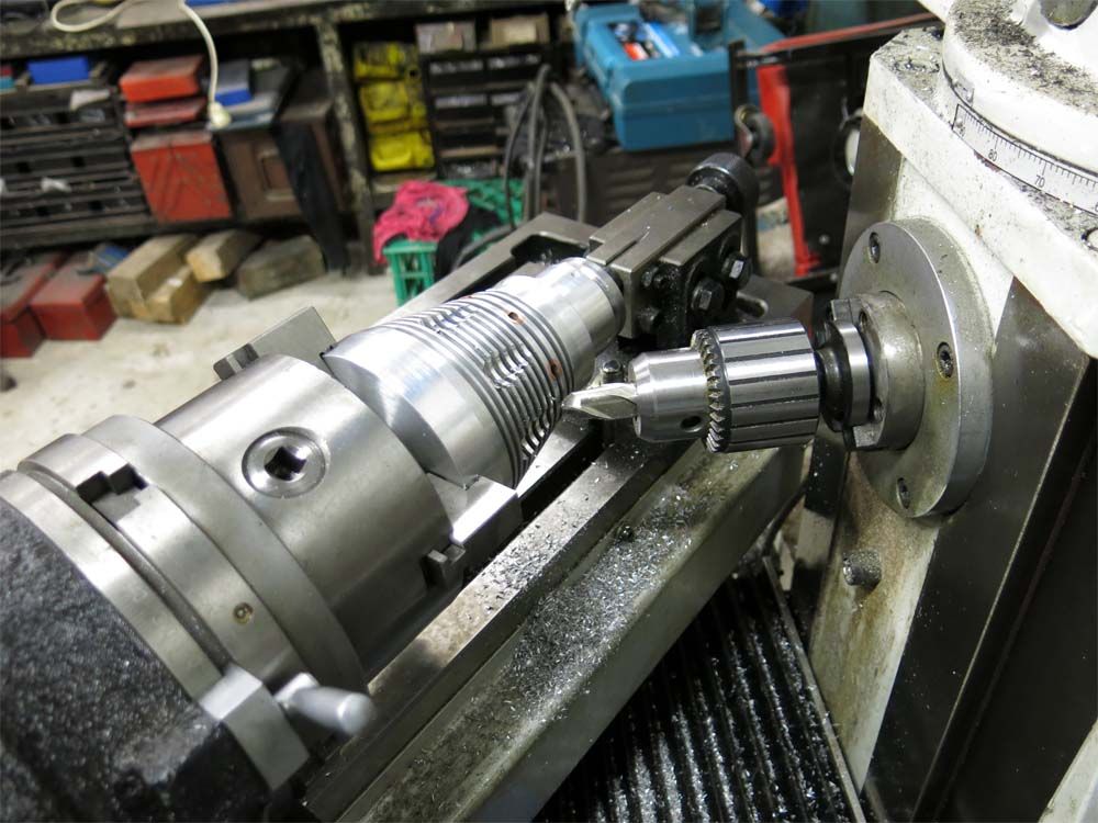
After snapping the 2mm tap off a new plan B was called for. New holes were drilled in a 4 bolt pattern instead of the original six and the drill used for the tapping size was 1.7mm instead of the correct 1.6mm. A pin chuck was used to hold the tap instead of the heavy tap holder. The tap went through like a hot knife through butter. Here is the second head drilled and tapped.
Note in the following pictures nothing is cleaned up so you are seeing the items warts and all

The rubber switch boot holder was machined up and the four holes drilled for the 2mm cap screws.

The heads of the 2mm cap screws were machined from 3.66mm diameter to 3.1mm diameter.

And here is the switch boot holder screwed into the head.

And with it machined to the profile off the head.

The switch boot retainer removed from the head.

To machine tear drops in the head the horizontal spindle was used.

The shape of the tear drops was determined by the amount I could swivel the bed. Another 3 or 4 degrees would of been nice but it just would not stretch that far around

One down one to go.

Lookin great! :+1:
Great work
You’re a freak! That’s so cool.
excellent great to see you back at it awesome job.
Steve does cool work :+1: for a freak.
Yes, I’m a freak at freaking out I’m going to make a mistake I cant fix. ![]()
That’s some seriously good looking work there! Keep it up! ![]()
Amazing progress! I especially like how that switch holder is made. In general I find it cool that you often make your parts bolted in instead of screwed in, it makes stuff look tough.
Wow, this is an amazing build ![]()
![]()
![]()
![]()
![]()
I’m making the light using my interpretation of how Justin built lights as much as possible hence the parts where possible are bolted together.
great build indeed!
What a joy to follow!
Beautiful!
Just down right STUNNING!!!
Super nice sir and yep…. thats how I think our friend would have done it.
Just nice! Thanks for sharing Steve!! TL
Its been a busy weekend here with a very belated Xmas party with a bunch of old friends.
There was just enough time left in the weekend to machine out the head of one light.
We started of by machine a hole 32mm in diameter to the final depth that the led will sit on. Its important here to get a good finish on the face for good heat transfer to the head.


Next we bored a hole to the depth and diameter that the two tapers will meet which are the close outline of the reflector. This will become clearer in the next couple of pictures.

The outer taper which was 18 degrees was then machined to where the second hole was bored to.

The inner taper was then machined. This was 30 degrees. The ends of the taper started at the end of the 18 degree taper and ended at the very inside coinciding with the 32mm diameter. Sometimes a plan actually works as designed. ![]()

The steps were then machined in for the reflector flange and lens.

The inside shape for the reflector closely follows the depth of the fins. You can also see the split bush in the chuck here holding the head so the head itself does not get damaged from the chuck jaws when tightened up.

This just gets better every time i look.