Hi guys, I have a Nitecore HC30 with a TA FET driver that I bought long time ago.
If I check the version, it blinks 1 time then 4 times, so it seems to be V1.4
I use it in ramping mode, everything is fine except I can’t disable strobe
I can mod any parameter, like choosing between ramping or modes set, adjusting the number of modes, or adjusting thermal management… but strobes are always there !
Example : from OFF, double-click to TURBO, then another double-click activate STROBE… even if I disable strobes
What target do I built anduril for to run it on these with full features (three channel)? My only exp with anduril is on a mini GT with its 2 channel driver.
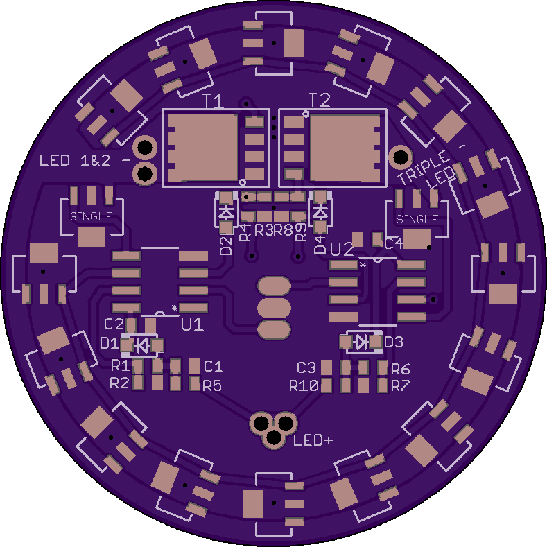
Hello again guys, I’m rebuilding my old Fenix TK45* and have a plan to use 2 complete TA driver circuits on one PCB, each independent of one another, each controlled by one of the lights two buttons.
One driver will run 2 of the heads with oslon KW’s in them, the other will run the 3rd head with a triple luxeon V.
Here’s my thought, regardless of which “light” is being used I would like turbo to turn on all LED’s, if I run each of the FET’s gates to each MCU’s pin3 [PB4] (then tune the FW’s ramp tables to stop modes at the top of the Nx7135 channels and ONLY use the FET’s for turbo) this should accomplish the desired bahavior without more in depth FW work. Seems simple enough, my question: do I need to tweak gate resistor values and/or do I need to have a resistor in line between the the two gate/PB4 nets?
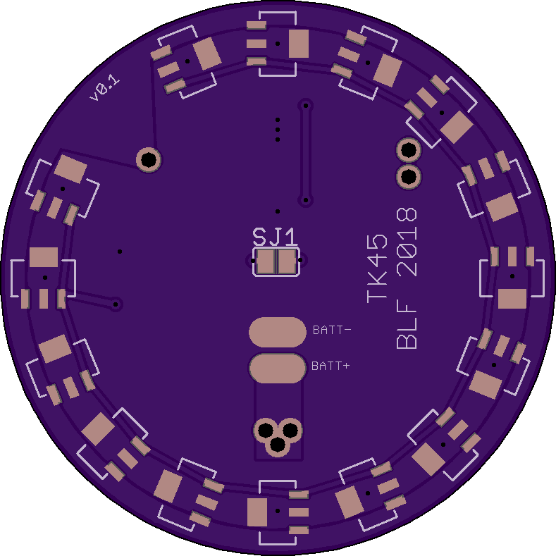
Btw incase I don’t end up liking the idea in use I have a solder jumper on the bottom of the board in the trace connecting the two gates, that way I can sever the connection without having to take anything apart.
*Note my TK45 is already converted to 1S lipo and currently runs a different 7135 based setup
you need in this case on both MCU outputs a diode and bridge to after it
otherwise the high signal of one MCU would be grounden with 20mA limit from the other
so cut the trace or open the 47 Ohms resistor on both drivers between FET and MCU and insert the diode and connect both FETs after diode and before 47 Ohms
To do:
Go over it again, it’s an expesive board to find a mistake on 8 minutes after I pay (how it usually goes)
Delete all extra parts TA points out in his post just below this one.
swap to a solder jumper normally closed (that requires being cut to open it) since I expect it to need to be shorted*
Add BLF driver key programming pads for both MCU’s
Move bottom 7135’s in ~5mm for body clearance
*The jumper on the bottom separates the NET connecting the FET’s in case I dont like it IRL.
Next question: What about R10 (R5 in a regular TA driver circuit) and the polarity protection diodes (D1 and D3) can the pairs of those be consolidated into only one of each? Will just one R5 allow enough current to operate both MCU’s?
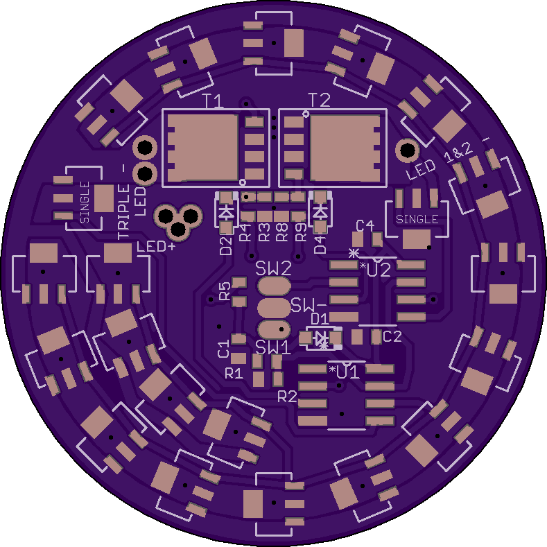
Updated to V04, now with 36 total 7135’s. Still haven’t ordered yet, redoing the back soon (the 7135’s sit to far out on the board to fit the head right) and adding a few more 7135’s back there too cause why not lol.
so many AMCs with no direct thermal path aka ground layer connecting the lights metal parts will be a problem heating the driver up a lot then go into thermal throttle
this is the reasom most SRKs have the AMCs poisitioned this way around
positioning the MCU more in the middle you can place around 21-22 on one side,
if you do 180° of driver one MCU and the other 180° with the other you got no problem signaling it on 2 layer
Just assembled a TA 17mm driver and it won’t turn the XM-L2 test LED on when connected on my test station.
- The assembled/soldered driver was not tested in a flashlight, but on a driver testing rig (if that makes a difference?). Hooked BAT+ to LED and BAT- to the driver ring. (rig resembles a “clicky light”, not eswitch)
- The backside (7135/battery side) is EMPTY, does this driver work without any AMCs on the back (only with FET +1)?
- I flashed “…/…/Bistro-Texas-Avenger-V1/Bistro Hex versions/bistro-texas-avenger.hex” from the .zip in the original post because I didn’t know what else to flash <- is this the correct file for a 1S setup? Which standard TA-Bistro FW should I flash for a standard 1S setup?
- Even though I double checked polarity on all parts, are there any issues? The Schottky is always my least favorite…
- attiny85 legs are bent, but not “wrapped” around or tucked under the attiny, they should make good contact (but might not?)
Checking/flashing with avrdude had no issues at all, flash command and fuses used:
Any glaring issues with wrong parts a fresh pair of eyes might be able to see?
I would be extremely grateful for any feedback. 4 pictures of the assembled driver are attached below:
Thank you so much for any help.
It would be great if this would work out somehow.