9-Up XP board for cheapie flashlights - Now with a driver on the bottom!

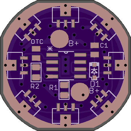
Remember those 9-LED cheap flashlights that used to be all the rage? You know, the super-cheap ones that are still stocked in every checkout line at every store, for a buck or two? Well, for the fun of it, I made a (very rough, so far) replacement PCB for those flashlights, so they could be upgraded from the 20mA 5mm leaded emitters to XP-size SMD emitters!

Edit: changed driver to V2.1 in which I cleaned up a bit and joined LED- to GND, which is also the thermal trace, using polygons. There is no longer an electrically neutral Thermal trace on this board. It will not work with most drivers without considerable effort. But, it’s not really meant to be used with a driver at all, as these cheap lights never have a driver in them and don’t generally have room for one. There is a board in post #10 that has a driver layout on the bottom as well as the LEDs on top. I’m not even sure that one will fit, height wise, but it’s probably the best bet for a regulated output.

This is a board I’ve always wanted to have, ever since I first came here to BLF a couple years ago. I’m probably going to have to clean this one up a bit before ordering. It looks like it was drawn in MS Paint by a kindergarten child. (Cleanup has been done) But, then again, these are very cheap lights we’re talking about! You should see what the stock PCB’s look like in those lights! Aesthetics aside, I’m not sure this board will even work, with the 15mil minimum copper distance to board edge that OSH Park specifies. It may take some finesse to get it to make electrical contact with the host! If/when I go back and re-work it, I may make it a tad bigger, so it can be sanded down to the right size and end up with copper at the edge. (Not making this board bigger, but the one below in post #10 is a little bigger) Since there’s no heat-sinking in the host anyway, it might be better to solder a copper ring to this board, improving both the electrical and thermal conductivity.

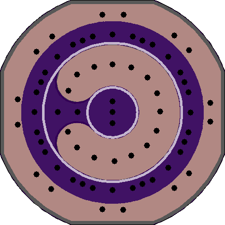
There are a couple reasons I made this board. First, as I said above, I wanted it to exist. Second, I just learned Eagle a little while back, and I wanted to practice and play around a little. Third, I had posted a thread last week about squaring off the circular PCB’s we use so to save a few pennies from OSH Park. I wanted to see just how hard it would be, so I started with this simple board. Let me know what you think!

Disclaimer, in case anybody sees this board and decides that they want to try this kind of mod: This board, at least the way it’s designed right now, is not meant for high current! It’s just a 2-layer FR4 board from OSH Park! I don’t know how much current it could take, but there are several reasons not to try too much. Not only is this board NOT a DTP copper MCPCB, but the light it is meant to inhabit is made very cheaply, is very thin, and has practically no heat-sinking at all to dissipate heat. And, this board is not even going to contact the ‘host’ all the way around, because of being squared off. Atop all that, this is a 9-LED board. Even what would normally be considered a conservative amount of power going to each LED, when added together, will probably be way too much for 9 LEDs in this close of proximity with no heat-sinking. If you stay with the 3AAA battery carrier which is usually included with these lights (and use alkalines in it), you’ll probably be fine, though! Also, if you can find one of the older generation 9-LED lights that was made with a thick body (yes, they used to be!), you could possibly get by with more current. These flashlights don’t have drivers, either. They are universally direct-drive, and have lots of intrinsic resistance. So, you’d be wasting a lot of power anyway, and producing even more heat.

Oh yeah, if you figure this board should have been 24mm diameter, and it is 22.5mm wide instead, then you’d save ~$0.46 on this board versus a round one. Not a lot, unless you regularly order lots of boards from OSH Park. Then, it can add up!

Mad! I’ve had some of those 9 LED fella’s - a couple had not too bad hosts but the guts were crp.
I would want to drill holes through all the centre pads and install some copper wire posts soldered to a copper heatsink doughnut stuck underneath the board. Maybe keep the centre LED for a different use, colour, indicator etc. (or am i going too far) :laughing:

I’ve thought about trying to shoe-horn a FET driver circuit and/or a three-channel RGB (three led’s of each color) onto this board somehow. Your idea of drilling out the center pads and adding copper wires and a heat-sink sounds interesting. I could make the center via of each LED pad bigger, so it doesn’t need to be drilled out, and a wire could be soldered in to each one. Since the center pad is electrically neutral, it could be merged with the LED- trace, which is on the outside edge of the board and is meant to contact the host. That would only work while it had no driver circuit. With a driver, the LED- needs to be isolated from the host/ground.

Pretty cool idea. My first mod (before discovering BLF) was a wire pill with a signal 3w emitter in one of those lights. I jogged with it a couple years. My hand absorbed the heat. Was nice in winter. You should consider unmasking the heat sink trace. That way it can be reflowed to a copper/brass washer for a thermal path to the body.

You know what would also be cool (continuing on with your idea). Make one of these guys for the Nichia 119’s. They have no thermal path. Your ground ring could be the thermal path.

Yeah, I thought of the Nichia 119’s as well. I have lots of those. It would be easier to design that board without the thermal pad, for sure.
If I redesign it for the XP’s thermal pads to connect to the host/body, I could merge the thermal trace with the LED- trace, so it would be able to conduct heat through the trace on the board as well as any add-on copper pieces that it might be soldered to. Right? That is, unless I were going to add a driver. In that case, I’d eliminate the LED- trace from the bottom and extend the thermal trace to the edge, using it also as the GND trace for the driver.

Another thing that might be interesting is making a triple or quad replacement board that fits Carclo or Ledil optics, with driver components on the same board to save height. If that could be made to work, it might actually make a useful flashlight!

If anybody gets bored with real flashlight modding, and wants to play with this board, you can download the Eagle .brd file directly from OSH Park. I don’t run CAM jobs or upload gerbers. :wink:

While you’re at it take a look at the AAA carrier, you can redo it for 3P and add some 7135 pads, wire rims, side pipes, etc.

Only thing I see, there is nothing limiting the current from the battery pack…when you put the 3xAAA carrier in, voltage will be above the LED’s Vf and full current will flow. I believe even on those craptastic normal LED’s there is a current limiting resistor somewhere on the board. Love the idea of squaring the circle to save a little on the board! I would think a single XP mule driven at even an anemic regulated 350ma from a single AMC7135 would be brighter than 9 of those 3mm LED’s driven at 20-30 mA, and with a large copper pour on both sides of the FR4 board, I think it would be able to handle the heat, at the very least spread it out to where it wouldn’t be a heat issue. I wonder what 9 XP’s in parallel driven at 350ma would look like…hmmmm

Awesome way to think outside the box! Keep it up man…the community always needs fresh ideas and designers

I think they even just use solder pads and a press fit in most cases for current path between the board and the body of the light

Correction (after further investigation)…it looks like they don’t have current limiting resistors…they appear to be wired in parallel and I have a sneaking suspicion that is why on some of mine more than a few LEDs are no longer illuminating, so it looks like they use the internal resistances of the batteries and other factors to prevent burning out the LED’s…hmmm

Seems you already are aware of this as well (just stumbled across this in a google search)
http://www.cree.com/~/media/Files/Cree/LED%20Components%20and%20Modules/XLamp/XLamp%20Application%20Notes/XLamp_PCB_Thermal.pdf
Biggest thing I just saw was “All XLamp LED packages have an electrically isolated thermal pad. The pad provides an effective channel for heat transfer and optimizes
thermal resistance from the LED chip junction to the thermal pad. The pad is electrically isolated from the anode and cathode of the LED
and can be soldered or attached directly to grounded elements on the board or heat sink system” so you could in fact use the center thermal slug pad tied into the ground ring in the copper pour to increase heat spread

Not sure if you know…the smallest drill size at OSHPark is .3302 as well…which helps in making small vias underneath the LED’s

Thanks WarHawk-AVG. I didn’t know what the minimum drill size is at OSH Park. That’s very useful information. I remember in the Mattaus tutorial, he mentioned that using more smaller vias would usually be better than fewer larger vias.

I started last night working on a new 9 XP board with driver components on the bottom. It will be a two-channel driver feeding to the LEDs on top and using 1x 7135 for better efficiency in the lowest modes plus 7 more 7135’s to fill out higher modes. As always, not all the pads have to be filled, but I like them to be there. I was thinking about making cuttable traces to isolate the one center LED on the one 7135 chip so that it can be lit independently if desired. I’ve got the bottom of the board wired with the driver, but I haven’t run traces on the top yet for the LEDs. I increased the size a bit from the board in the OP here, so the ‘OSH Park edge’ (The 15-mil no-copper keepaway from edge of PCB) can be filed away, leaving copper to the edge of the board. I also made the copper edge on the bottom GND trace the same squared off circular shape as the ‘OSH Park edge’ for a little better aesthetic appeal.

If it turns out the way I’m hoping, it could be a seriously useful board. I’ll upload it here when I get it done.

Well, here’s a new board with 9 XP sized pads for LEDs on top and a simple 2-channel driver circuit on the bottom. Channel one is a single 7135 and channel two is 7x 7135 chips. There is a cut line indicated in the silk screen on the top of the board. If you cut the trace under that line, the single 7135 feeds the single XP in the center independently. Also, this board will most likely require filing down the diameter a bit in order to fit.

My LED traces are thin, I realize. Hopefully they’re not too thin, or maybe somebody would like to help me figure out how I can re-work it so all the LED traces can be wider. There’s a lot happening on this board, so space is severely limited. Also, the LEDs have to be where they are in order to work with the stock “reflector”. So moving them around, or the almost obvious - moving them outward - to make room for wider traces can’t happen.

Anyway, I thought I ’d try this, even though it’s super crazy to even think about putting a board like this in one of those cheap flashlights that this board is made to fit. Oh well, here it is. Waddaya think?

Edit: Oh yeah, forgot to mention about the two B+ pads on the bottom. You must bridge across those with a wire or some kind of metal. This idea shamelessly stolen from MikeC. The two B+ pads must be connected electrically by a wire bridge in order for everything to get power. A stiff wire bridge will also act as the Battery positive contact, supported by the MCU. Make sure you program the MCU properly the first time. :smiley:

HaHa! If you populate this board with 8x 380mA AMC7135 chips for a total of 3.04A, then according to Cree PCT, even 9x XP-E2 R3 can reach ~1200 lumens from this set-up! With 9x of (highest bin) XP-L or XP-G3, it would be ~1700 lumens! Since each emitter would only get ~333mA this way, the LEDs are very efficient, and even heat might not be too much of an issue. The only way to know for sure would be to try it, I guess. But, it’d be a relatively expensive experiment for such cheap ‘hosts’ I think. :money_mouth_face:

Update! I learned how to use polygons! As I said before, this board is one I’ve been thinking about since almost the beginning of my time here at BLF. At this point, I’m really just working on it for the sake of learning Eagle. Polygons in Eagle make a lot of things easier, and the results look better. So, I changed a lot of the traces that I had cobbled together with circles, arcs, rectangles, and ‘wires’ into polygon pours and made a few other adjustments along the way. The new board, and a little more info about it, is in the OP.

Wow! Haven’t been here for a bit. Pretty cool. I’m in a rush right now, but I will be revisiting. Thanks for making something unique (and I think useful) while you develop your Eagle skills.