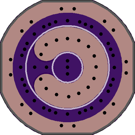
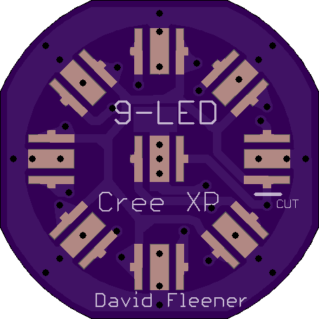
Remember those 9-LED cheap flashlights that used to be all the rage? You know, the super-cheap ones that are still stocked in every checkout line at every store, for a buck or two? Well, for the fun of it, I made a (very rough, so far) replacement PCB for those flashlights, so they could be upgraded from the 20mA 5mm leaded emitters to XP-size SMD emitters!
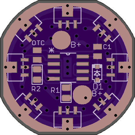
Edit: changed driver to V2.1 in which I cleaned up a bit and joined LED- to GND, which is also the thermal trace, using polygons. There is no longer an electrically neutral Thermal trace on this board. It will not work with most drivers without considerable effort. But, it’s not really meant to be used with a driver at all, as these cheap lights never have a driver in them and don’t generally have room for one. There is a board in post #10 that has a driver layout on the bottom as well as the LEDs on top. I’m not even sure that one will fit, height wise, but it’s probably the best bet for a regulated output.
This is a board I’ve always wanted to have, ever since I first came here to BLF a couple years ago. I’m probably going to have to clean this one up a bit before ordering. It looks like it was drawn in MS Paint by a kindergarten child. (Cleanup has been done) But, then again, these are very cheap lights we’re talking about! You should see what the stock PCB’s look like in those lights! Aesthetics aside, I’m not sure this board will even work, with the 15mil minimum copper distance to board edge that OSH Park specifies. It may take some finesse to get it to make electrical contact with the host! If/when I go back and re-work it, I may make it a tad bigger, so it can be sanded down to the right size and end up with copper at the edge. (Not making this board bigger, but the one below in post #10 is a little bigger) Since there’s no heat-sinking in the host anyway, it might be better to solder a copper ring to this board, improving both the electrical and thermal conductivity.
There are a couple reasons I made this board. First, as I said above, I wanted it to exist. Second, I just learned Eagle a little while back, and I wanted to practice and play around a little. Third, I had posted a thread last week about squaring off the circular PCB’s we use so to save a few pennies from OSH Park. I wanted to see just how hard it would be, so I started with this simple board. Let me know what you think!
Disclaimer, in case anybody sees this board and decides that they want to try this kind of mod: This board, at least the way it’s designed right now, is not meant for high current! It’s just a 2-layer FR4 board from OSH Park! I don’t know how much current it could take, but there are several reasons not to try too much. Not only is this board NOT a DTP copper MCPCB, but the light it is meant to inhabit is made very cheaply, is very thin, and has practically no heat-sinking at all to dissipate heat. And, this board is not even going to contact the ‘host’ all the way around, because of being squared off. Atop all that, this is a 9-LED board. Even what would normally be considered a conservative amount of power going to each LED, when added together, will probably be way too much for 9 LEDs in this close of proximity with no heat-sinking. If you stay with the 3AAA battery carrier which is usually included with these lights (and use alkalines in it), you’ll probably be fine, though! Also, if you can find one of the older generation 9-LED lights that was made with a thick body (yes, they used to be!), you could possibly get by with more current. These flashlights don’t have drivers, either. They are universally direct-drive, and have lots of intrinsic resistance. So, you’d be wasting a lot of power anyway, and producing even more heat.


