Just a thought if you’re going to use a stiff wire as battery contact… I used a pretty large via to stick the wire in. Your design doesn’t appear to have a large via for a stiff + wire through. If that is your intention you might want to add one, because without one it might not be so easy to get that wire to stay put.
I just JB a copper pad to the top of the chips and wire to that.
That’s probably a better idea as it saves some space.
Yeah, I haven’t tried anything like this before. So, I really don’t know what will work, but I know it will have to be secured somehow besides just the solder. I was thinking either a stiff wire soldered and then epoxied to the board, or a copper “plate” cut out of a piece of copper pipe, soldered and epoxied.
I realized a while back that the driver was not properly designed for the little zoomie I wanted to put it in, so I’m working on a re-design, and I also switched to a FET instead of the two 7135’s I had before. This is W.I.P. so parts of it aren’t done yet. It’s looking like it’s going to be difficult to make this driver PCB “single sided” (plus the LED on the other side) like I wanted. I could change the FET to a NXP, which is smaller, but I already have some extra FET drivers laying around that I could steal parts from to build this, and they all have SiR800DP on them.
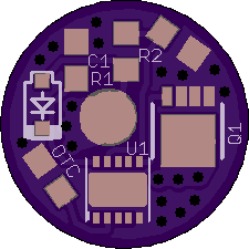
Right now, the positive input (and LED+) is the top left corner, between the diode and R1. That’s what I really need to make more/better accommodation for at this point, because it somehow needs to contact the positive cell top, which will hit center of the driver. The ground ring will be on the other side anyway, where there’s plenty of room, so no problem there. And the FET’s output also has plenty of space, since it just has to go through the board and connect to the LED. By the way, this board is smaller, too. It’s now only 11mm diameter (plus the OSH Park Edge™). Anybody got any ideas? After I get it finished, I might make one with the battery contacts on the flip side, like a regular driver. AFAIK this will be the smallest single sided programmable FET driver we’ve got.

Well, here’s one that’s laid out like I had before, when it had 2x7135 chips. I should have just done this first, but I didn’t think the FET would fit where the 7135’s were. I was wrong. It gives me a bit more room for LED+ by moving it to the top. OOPS! I just realized that I haven’t fixed my labels yet. I’ll get that cleaned up before uploading to OSH Park.

If you want to upload the eagle files, i can give it a proper look if you want.
Here is my brd file. I did make a custom SO8 part for the SiR800DP because I didn’t like the generic SO-08 part that was available in the Eagle libraries. You may or may not want to use that. It’s here if you do. Let me know if the sch file would be useful to you. I can upload it as well. https://drive.google.com/open?id=0B96jfkvZZEJ7ZmZzbjhXblpIZGM
Here’s V1 of the new 11mm driver board. The brd file is available at the OSH Park link, embedded in the pics. I did change to LFPAK33 for the FET. I figured I could buy some from Richard when the time comes. I still haven’t done all the labeling that I’d normally do, but if I end up making any more changes, I can add the rest of the labeling then.
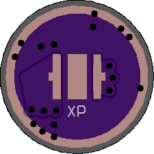
Without the schematic it was a bit hard to figure out but i think oriented like this it should work while still giving you ample room for pads and vias with minimal trace lengths:

Only one signal has a longer run but i assumed it is just a control signal.
The ground return is kept as short as possible.
If do not know if you can do vias in (thermal) pads, if you can do vias in pads this can be further optimized.
Thanks PeterF!
I know the FET saves space over the 7135(s) but it commits you to a pwm only situation since there’s no way you can run it flat out. Even 1 x 7135 is probably maxing out this small board with no metal core. A maglite solitaire gets plenty hot using two chips feeding an led on a10mm copper sinkpad. Why the switch?
I guess, as far as a ‘reason’ for the switch, it’s just that I wanted to be able to claim a bigger max output. I know that these 10180 cells can push at least ~1.5A into the right load, and it didn’t seem fair to restrict it to merely half that. Anyway, I could run it flat out, if I wanted to, just maybe not for very long. ![]()
Was not that hard to figure out, i am not a pro but i have been doing my own layout work for the past 10 years or so.
Still learning new things every day though.
Cou could to a few tricks with spring contacts or bend metal strips to get a center pad with the needed current capacity on a small footprint.
If you can put vias in the pads you can get very creative about the whole thing as well.
Would have routed it completely but i did not know if you need pads somewere so i just shoved i together as tight as possible.
You got a bunch of copper->dimension distance set, if you can get the board with plated edges and pull the copper over and around the sides.
Well, I feel stupid. Somehow, I got into my head that there weren’t any single sided drivers in this size. I’ve looked at the BLF Tiny10DD (and Tiny12DD). Those are two-sided drivers. But I guess I forgot that there’s also the MTN-10DD (and 11 and 12), which is single sided. I probably could have just used that driver, instead of designing my own. Oh well, I guess it doesn’t hurt to have one more option around. :person_facepalming:
Your driver also includes the led.
Went ahead and ordered some of these boards from OSH Park. They are tiny! Even reflow soldering this one is gonna be FUN! 
Cute little things. Take another pic when populated and post.
Oh yeah. I’m probably going to add a few pics to the Tiny Zoomie mod thread I did a while back. That’s what this driver was meant for. I bought some more of those zoomies, these boards, and the components to do a couple of them. The coolest part is that this board should just be a drop-in upgrade once it’s populated. So, the whole mod will only take minutes to complete, if I don’t mess with tail-spring bypass or anything like that.
Cool :+1: