!!! Update April 13, 2017 !!! I need help again. See post #71. I’m trying to re-design my driver board, because I realized it wasn’t going to work. I decided to upgrade to a FET at the same time. I need some help trying to arrange the components on the tiny (now ~11mm) board.
!!! Update January 20, 2017 !!! I added even more vias to the alternate board. The newest alternate board is shown in post #62.
!!! Update January 19, 2017 !!! I added some more vias to the alternate board as Rufusbduck suggested. The newest alternate board is shown in post #59. I guess I need to go back and add vias to the regular driver board as well.
!!! Update January 16, 2017 !!! The latest revision of this driver is in post #47. And, there’s another board in post #50 which is a bit different.
!!! Update January 06, 2017 !!! The newest board design is in post #42 now. All components are within 5.5mm of center so it can be sanded down to 11mm diameter. Just sanding down the OSH Park Edge™ will leave you with 12.5mm diameter.
!!! Update in post #29 !!! Sorry, the board in post 29 won’t work. See post 40 from DEL.
Hey guys. I just wanted to post this up in case someone might be interested in it. It’s not for the barn burners. But not everybody wants to light up the whole world at once from a single hand-held device. Sometimes, just a little light is all you might need. Also, since I’m still very new at driver building, let alone driver designing, I’d like somebody who does know a little about this stuff to give me some feedback if ya don’t mind.
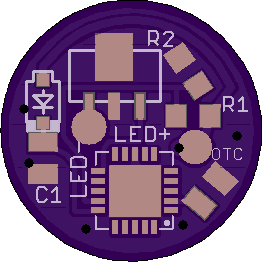
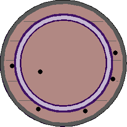
So, here we go. The driver outline is 13.28mm, according to OSH Park. Just sand down the OSH Park Edge™ to make this a 12.5mm diameter linear LED driver with only a single AMC7135 chip to regulate current for very small flashlights. The MCU is Atmel attiny13a MMU. The resistors R1 and R2 have a 0603 footprint, but 0805 resistors will fit. I used 0805 footprint for both Capacitors C1 and OTC.
I was really hoping to get a simple (old style around here) linear driver down to 11mm if possible, but I haven’t figured out how to squeeze this stuff any tighter, even with using the smaller MMU footprint of the tiny13 MCU. If any of you Eagle Masters wouldn’t mind helping me figure out how to cram this stuff into a tighter space, I would appreciate it. I know putting some components on the other side would work. Two sided drivers as small as 10mm have already been done, but I’m trying to keep this single sided.
I made this driver for (hopefully) modding a little Lux-Pro zoomie I found at Lowe’s a few weeks back. It has a rear clicky switch, and uses four little button cells to directly power a cheap LED. It’ll take some work, but I’m planning to squeeze in some kind of driver (maybe this one) and a better LED, and replace the button cells with a single 10180 Li-Ion to make around 150 LED lumens. Alternatively, I thought about stringing multiple LEDs inside a tube epoxied into the bezel to make a sorta stick light that will be small enough to pocket. With the added efficiency from splitting the current, it might reach close to 200lm output.
Here’s what I’ve got so far: